


B-4 B-4
OPERATION
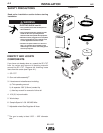
Friction Brake Adjustment
With wire spool installed on the spindle shaft and the
wing nut loose, turn the spool by hand while slowly
tightening the wing nut until a light drag is felt. Tighten
the wing nut an additional 1/4 turn.
Note: When properly adjusted, the brake should pro-
vide only enough drag to prevent overrun of the spool
and excess slack in the wire. Too much drag may
result in wire feeding problems, and may cause pre-
mature wear of wire drive system components.
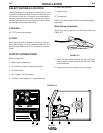
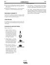
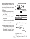
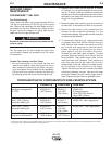
Wire Threading
Refer to Figure B.4
1. Release the Spring Loaded Pressure Arm (1)
rotate the Idle Roll Arm (2) away from the Wire
Feed Drive Roll (3). Ensure that the groove size in
the feeding position on the drive roll matches the
wire size being used. See Maintenance section for
further information.
2. Carefully detach the end of the wire from the
spool. To prevent the spool from unwinding, main-
tain tension on the wire until after step 5.
3. Cut the bent portion of wire off and straighten the
first 4” (100 mm).
4. Thread the wire through the ingoing guide tube
(4), over the drive roll (3), and into the outgoing
guide tube (5).
5. Close the idle roll arm (2) and latch the spring
loaded pressure arm (1) in place. Rotate the spool
counterclockwise if required to take up extra slack
in the wire.
6. The idle roll pressure adjustment wing nut is facto-
ry set to approximately five full turns from where
the wing nut first engages the threads of the pres-
sure arm (1). If feeding problems occur because
the wire is flattened excessively, turn the pressure
adjustment counter-clockwise to reduce distortion
of the wire. Slightly less pressure may be required
when using 0.023 – 0.025" (0,6 mm) wire. If the
drive roll slips while feeding wire, the pressure
should be increased until the wire feeds properly.
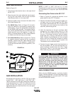
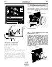
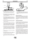
7. Refer to Figure B.5. Remove gas nozzle and con-
tact tip from end of gun.
When inching the welding wire, the drive rolls, the
gun connector block and the gun contact tip are
electrically energized relative to work and ground
and remain energized for several seconds after
the gun trigger is released.
8. Turn the SP-175T ON (“I”).
9. Straighten the gun cable assembly.
10. Depress the gun trigger switch and feed welding
wire through the gun and cable. (Point gun away
from yourself and others while feeding wire.)
Release gun trigger after wire appears at end of
gun.
11. Turn the SP-175T OFF (“O”).
12. Replace contact tip and gas nozzle.
13. Refer to Figure B-6. Cut the wire off 3/8”– 1/2” (10
– 13 mm) from the end of the tip. The SP-175T is
now ready to weld.
WARNING
FIGURE B.4
The Wire Drive Feed Roll
can accommodate two wire
sizes by flipping the wire
drive feed roll over.
FIGURE B.5
Gun Handle
Gas Diffuser/
Contact Tip
Gas Nozzle
1
2
3
4
5
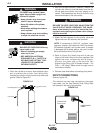
SP-175T