


PAGE F-1 Wiring Diagram
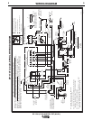
Wiring Diagram M18221 is replaced by M18716, copy of which is included on
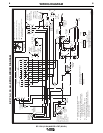
page 5 of this addendum. Wiring Diagram M18931 is replaced by M18932, copy
of which is included on page 6 of this addendum.
P
AGE P-259-A.1 or P-297-A.1
Present code numbers for this machine are 10337, 10403, 10489 and 10633.
Specific part number changes are listed below.
P
AGE P-259-B.1 or P-297-B.1
Spot/Stitch Timer Kit is changed from K695-1 to K695-3.
PAGE P-259-C.1 or P297-C.1
Item 1 Case Side replaced by L10150
Item 3
Wiring Diagram (Codes 10337 & 10403) replaced by
M18716 (SP-170T)
Item 3
Wiring Diagram (Codes 10489 & 10633) replaced by
M18932 (SP 170-I)
Item 4 Case door replaced by L10151
Item 5 Procedure sheet replaced by L10153
(located inside spool cover)
PA
GE P-259-D.1 or P297-D.1
Item 6 Center panel (SP-170T) replaced by L10149
Item 6 Center panel (SP 170-I) replaced by L10520-1
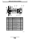
Items 9-17 Spindle components replaced by
See Attached Parts List on Page 4
The following items are not illustrated:
New item 23 Spindle support S23710
New item 24 Spool Cover (includes Backing Plate)*
L10152
New item 25 Insulation (for PC Board) S22740
New item 26 Compartment Panel M18228
* Order Procedure Sheet separately per Page P-259-C.1 (above)
P
AGE P-259-E.1 or P297-E.1 Item 2 Case Back & Bottom replaced by G3046-1
3
SP 170-I (12 IN.) AND SP-170T (30 LB.)
3
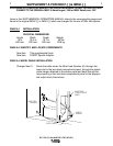
PAGE B-3 or B-4 FRICTION BRAKE ADJUSTMENT
Item 1 to 3 replaced by: TENSION ADJUSTMENT. Adjust the brake ten-
sion with the wire spool thumb screw, located inside the retaining collar,
until the wire reel turns freely but with little or no overrun when wire feed-
ing is stopped.
Wire spool spindle
8” wire spool
S18221 Spindle Adapter
Collar
Be sure that this stud engages the holes
in the wire spool and spindle adapter.
Figure B.3a
SUPPLEMENT A FOR IM537-[ ] & IM591-[ ]