


A-2
A-2
INSTALLATION
Read entire installation section before starting
installation.
SAFETY PRECAUTIONS
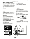
IDENTIFY AND LOCATE
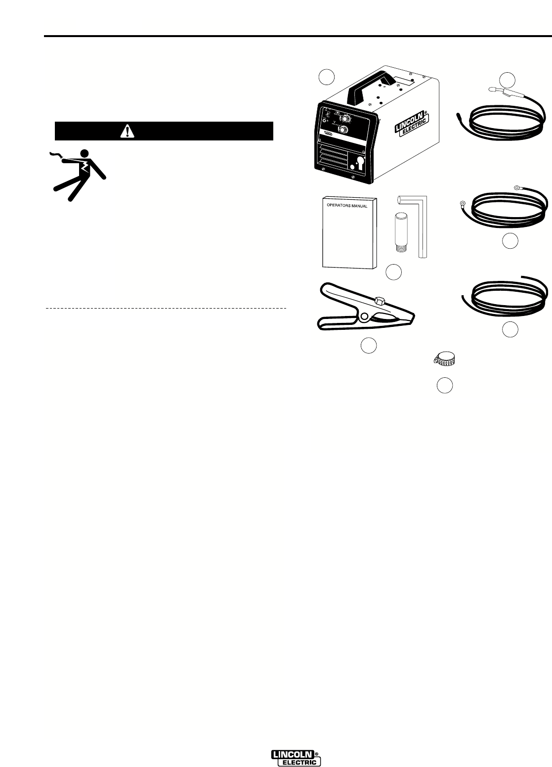
COMPONENTS
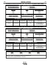
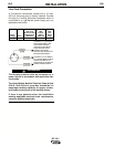
If you have not already done so, unpack the SP 170-I
from its carton and remove all packing material
around the SP 170-I. Remove the following loose
items from the carton (see Figure A.1):
1. SP 170-I or UWW-170
2. Gun and cable assembly
(1)
3. Literature and miscellaneous including:
a) This operating manual
b) Contact tips:
SP 170-I UWW-170
2 0 .025” (0.6mm) for solid wire
1 2 .030” (0.8mm) for solid wire
2 0 .035” (0.9mm) for cored wire
02
.045” (1.2mm) for cored or solid wire
c) 5/64” (2.0 mm) Hex key wrench for removal of
drive roll.
4. 10 ft (3,0 m) work cable.
5. Work clamp.
6. 14.0 ft (4.3 m) .19” (4.8 mm) dia. gas hose
7. 2- Hose clamps
(1)
The gun is ready to feed .030" (0.8mm) diameter
wire.
ELECTRIC SHOCK can kill.
• Only qualified personnel should perform
this installation.
• Only personnel that have read and under-
stood the SP 170-I Operating Manual
should install and operate this equipment.
• Machine must be plugged into a receptacle
which is grounded per any national, local
or other applicable electrical codes.
• The SP 170-I power switch is to be in the
OFF (“O”) position when installing work
cable and gun and when connecting power
cord to input power.
WARNING
FIGURE A.1
SP
170
SP
1
7
0
-
I
E
WE
L
DIN
G A
M
P
R
A
N
GE
WELDING AMP
R
A
N
GE
1
2
4
6
7
3
5
SP 170-I