


B-5
OPERATION
B-5
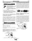
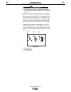
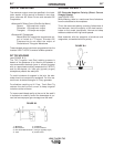
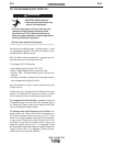
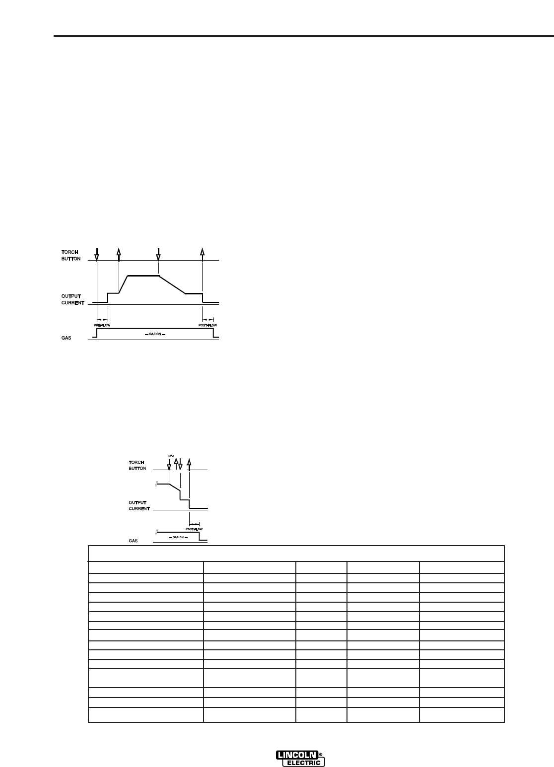
3. Press and hold the TIG torch trigger when the main
part of the weld is complete.
The machine will now decrease the output current
at a controlled rate, or downslope time, until the
Finish current is reached. Both the Downslope Time
and the Finish Current are presettable. This Finish
current can be maintained as long or as short as
necessary.
4. Release the TIG torch trigger.
The output current of the machine will turn OFF and
the gas valve will remain open to continue the flow
of the shielding gas. The duration of this postflow
time is adjusted by the Postflow parameter. This
operation is shown in (4 step diagram 1).
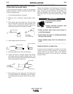
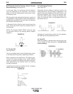
Possible variations of this standard sequence are
shown below.
By releasing and re-pressing the TIG torch trigger dur-
ing the downslope step, the output will immediately
drop to and hold at the Finish Current. Releasing the
trigger will turn off the output and begin postflow. This
operation shown in (4 step diagram 2)
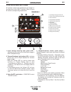
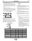
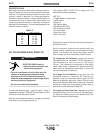
9. Welding selection button - Permits selection of
the welding mode. The LED beside the symbol con-
firm the selection:
• Stick
• TIG DC
• TIG AC
10. Electrode Connection (Negative) - For quick dis-
connect system using Twist-Mate
TM
cable plugs
with gas pass through for TIG Torches.
11. Remote Control Connector - For the connection
of a Lincoln Foot Amptrol, Hand Amptrol or Arc
Start Switch. See the ACCESSORIES section for
available options.
12. Electrode Connection (Positive) - For quick dis-
connect system using Twist-Mate
TM
cable plugs
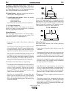
13. Welding Parameter Display - LED’s show which
mode or welding parameter is activated for adjust-
ment.
• If it is necessary to modify the welding parame-
ters "Item 13":
- Wait four seconds after the LED’s on the
panel have gone out, the welding current
LED will be lit.
- Press the SETUP/Parameter push button
"Item 4"; every time the push button is
pressed, one of the LED’s in the diagram
“Item 13” comes on (in clockwise sequence)
and the value of the parameter appears on
the Digital display "Item 6". Stop at the
desired parameter.
- Rotate the Output/Parameter Adjust Knob"Item
5" and modify the parameter value.
- Press the SETUP/Parameter "Item 4" push
button again to pass to another parameter,
or wait five seconds and the Weld Current
LED will come on again.
V205-T AC/DC TIG
4 STEP DIAGRAM 1
4 STEP DIAGRAM 2
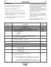
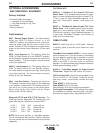
WELDING PARAMETER DEFAULTS AND RANGES
PARAMETER VALUE MIN MAX DEFAULT
START CURRENT AMPS 6 MAX 15
UPSLOPE SEC. 0 10 0.2
WELD CURRENT* AMPS 6 MAX 100
DOWNSLOPE SEC. 0 10 1.0
FINISH CURRENT AMPS 6 MAX 8
POSTFLOW SEC. 0.2 60 5.0
PULSE FREQUENCY HZ 0.1 500 0.5
% ON TIME % 5 95 50
BACKGROUND CURRENT
% OF WELD CURRENT
1 100 20
AC FREQUENCY HZ 20 150 100
AC BALANCE % EN 35 85 65
(EN = Electrode Negative)
MODE DC TIG
TRIGGER 2 STEP
LOCAL / REMOTE LOCAL
(1)
(2)
(3)
(4)
* Maximum Weld Current can be limited by input voltage, Welding Mode, AC TIG waveform and AC TIG frequency.