1
DEMO MANUAL DC101
SMART BATTERY CHARGER
LT1511 Level 2, Smart
Battery Charger Demo Board
with SMBus Interface
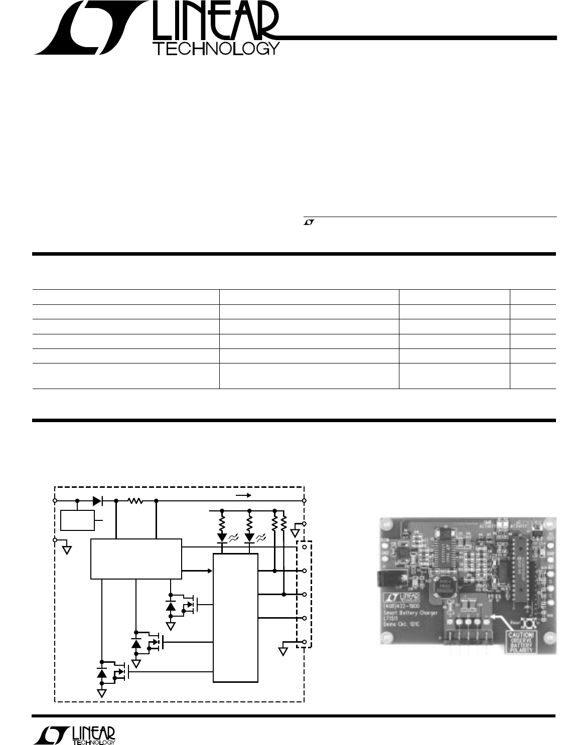
BLOCK DIAGRA A D BOARD PHOTO
U
W
DESCRIPTIO
U
The DC101 board is a standalone Smart Battery charger
that receives Charging Voltage(), Charging Current() and
AlarmWarning() commands from the Smart Battery via
the System Management Bus (SMBus) and sets charging
current and voltage accordingly. The charger continu-
ously monitors the built-in thermistor in the battery. The
thermistor information is used by the software to inhibit
charging at temperature extremes and to set charging
strategy for different battery chemistries.
, LTC and LT are registered trademarks of Linear Technology Corporation.
PERFOR A CE SU ARY
UWWW
PARAMETER CONDITIONS MIN TYP MAX UNIT
Input Voltage 16 24 27 V
Input Current Hardware Limited 2 A
Output Current Software Limited 0 2.5 A
Output Voltage Software Limited 4 20 V
Thermistor Resistance Ni-MH Battery 3 30 kΩ
Li-Ion Battery 0.5 1 1.5 kΩ
VOLTAGE PWM
CURRENT PWM
SHUTDOWN
DC OUT
GND
C SMBus
CLOCK (SCL)
D SMBus
DATA (SDA)
T THERMISTOR
BATTERY
CONNECTOR
+
–
5V
SMB µP
Q1
Q2
Q3
DC101 BD
LT
®
1511
CHARGER
FROM
WALL
CUBE
R10
SYSTEM CURRENT
5V
LT1129
+
–
26 14
15
2
11
PIC16C73
13
12
DC101 Smart Battery Charger
Component Side


