


4
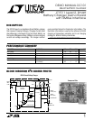
DEMO MANUAL DC101
SMART BATTERY CHARGER
REFERENCE
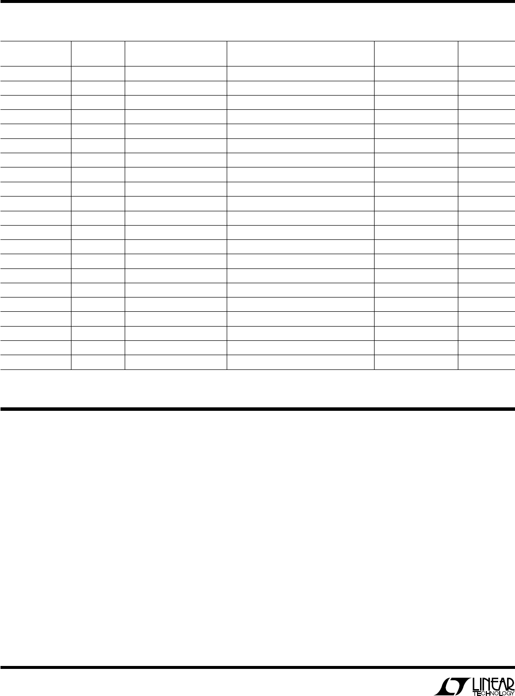
DESIGNATOR QUANTITY PART NUMBER DESCRIPTION VENDOR TELEPHONE
R5, R6, R14 3 CR32-331J-T 330Ω 1/8W 5% Resistor AVX (803) 946-0524
R7 1 BCR1/8-3322F-T 33.2k 1/8W 1% Resistor Beckman (714) 447-2345
R8 1 LR2010-01-R033-J 0.033Ω 1/2W 5% Resistor IRC (512) 992-7900
R9 1 CR32-104J-T 100k 1/8W 5% Resistor AVX (803) 946-0524
R10 1 LR2010-01-R050-J 0.05Ω 1/2W 5% Resistor IRC (512) 992-7900
R11 1 CR32-511J-T 510Ω 1/8W 5% Resistor AVX (803) 946-0524
R12 1 W1206R-03-1003-B 100k 1/8W 0.1% Resistor IRC (512) 992-7900
R13 1 W1206R-03-1433-B 143k 1/10W 0.1% Resistor IRC (512) 992-7900
R15 1 W1206R-03-2152-B 21.5k 1/10W 0.1% Resistor IRC (512) 992-7900
R17 1 CR32-1051F-T 1.05k 1/8W 1% Resistor AVX (803) 946-0524
R19, R20 2 CR32-2000F-T 200Ω 1/8W 1% Resistor AVX (803) 946-0524
R21, R22, R25 3 CR32-223J-T 22k 1/10W 5% Resistor AVX (803) 946-0524
R23 1 CR32-220J-T 22Ω 1/10W 5% Resistor AVX (803) 946-0524
R24, R26 2 CR1206-103J 10k 1/8W 5% Resistor Dale (605) 665-9301
S1 1 MJTP1230 PB Switch MORS-ASC (617) 246-1007
TP1 to TP5, E1 to E7 12 1502-2 Turret Testpoint Keystone (718) 956-8900
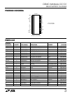
U1 1 PIC16C73-20SP Microcontroller IC Microchip (602) 786-7200
U2 1 LT1511 Battery Charger IC LTC (408) 432-1900
U3 1 LT1129IST-5 Voltage Regulator IC LTC (408) 432-1900
XU1 1 7167-14-G2 Sockets IC Comm Con (818) 301-4200
Y1 1 MA-505-4.00M-C2 4MHz Crystal Epson (USA) (310) 787-6300
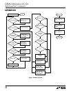
OPERATIO
U
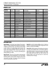
Input Voltage: The nominal input voltage of the board is
24V DC. The input voltage must be higher than the battery
voltage by a minimum of 3V. The minimum input voltage
is 16V, limited by the undervoltage lockout circuit in the
LT1511 and set by resistors R16, R17 and R18. The
highest input voltage is 27.4V, limited by the maximum
input voltage of the LT1511. The input is protected against
reverse polarity up to 30V.
Input Current: The sum of the system current and the
charger input current is limited by the LT1511 to 2A. When
both the system current and the charger input current
requirements are high, the charger reduces the charging
current to meet the 2A current limit.
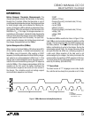
Red LED: A red LED indicates SMBus activity. It lights up
for about 1 second when the charger recognizes its own
address (12 hex) on the SMBus.
Green LED: A flashing green LED indicates microproces-
sor activity and charger status. Fast blinking (approxi-
mately 8Hz) indicates normal microprocessor activity and
either trickle charge or shutdown charger status. After
valid voltage and current data have been received, the
blinking speed of the LED slows down to about 2Hz,
indicating normal charging.
PARTS LIST