


If desired, you can extend the straight-line guide
by attaching straight pieces of hardwood to each
arm of the guide. Remember to leave a sufficient
opening for the router bit to work and for an
unobstructed view of the cutting area.
After the first pass, rotate the stop setting to the
next tallest stop and continue until the desired
depth is achieved.
Regulate the upper limit of the router body by
rotating the upper limit knob. The ideal upper limit
is when the base of the router bit just clears the
router base when the router height locking level is
released.
Safety note
1. Do not raise the upper limit above the position
described above.
2. Before operating the router, make sure it can
automatically ascend to the upper limit
referred to above.
3. Excessive cutting depth leads to motor
overload and drag on the shaft. Limit each
pass to a maximum depth of 9/16” or 15mm.
Make multiple passes to achieve the desired
results. The maximum total plunge depth for
this router is 2”.
4. Use appropriate router bits for the job. Never
attempt a plunge cut deeper that the length of
the cutting edge of the bit.
5. Make sure the shaft lock button is fully
released and the shaft rotates freely before
each use.
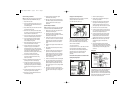
Operation
Place the router base on the work piece while
keeping the bit free and away from the material.
Switch the tool on and wait until it reaches full
speed. The work piece must be securely
anchored. The work piece must be on the left side
of the router bit when looking in the direction of
the feed for the edge to be cut (Fig.4).
Cutting tips: Guide the router slowly and evenly
to obtain a quality cut and to avoid overloading the
tool. Keep moving the tool to avoid burning or
discolouring of the wood surface. Proper speed
depends on the size of the bit, the type of wood,
and the cutting depth. You may want to
experiment on a similar piece of waste wood first,
to get some practical experience.
When using a straight-line trim guide, install it on
the right side of the router. Keep the edge of the
work piece in view by looking in the direction of
the feed.
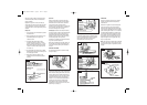
STRAIGHT-LINE GUIDE:
Use the straight-line guide for optimum straight
plunge cuts (Fig.5).
Attach the straight-line guide to the base module
guide mount with the wing nut (B); loosely tighten.
Attach the base module guide mount to the router
base by sliding the two parallel rods through the
corresponding opening in the router base; loosely
tighten all three wing nuts (A). Slide the guide
module in or out to achieve the desired distance
between the router bit and the straight guide
before tightening wing nuts (A). To make fine
adjustments, turn the trimming screw knob, then
tighten wing nut (B) (Fig. 6).
Fig. 4
Fig. 5
Fig. 6
Fig. 7
Fig. 8
Fig. 9
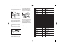
TRIM-GUIDE:
Use the trim guide for optimum curve cutting or
trimming. The guide roller ensures perfectly
contoured cuts.
Attach the trim guide to the base module guide
mount with the wing nut (B); loosely tighten.
Attach the base module guide to the router base
in the same way described above for the straight
guide. Slide the guide module in or out to achieve
the desired distance between the router bit and
the trim guide roller before tightening the three
wing nuts (A). Fine-tune the distance by turning
the trimming screw knob; tighten wing nut (B).
Adjust the height to the trim guide roller using
wing nut (C) (Fig.7/8/9).
Note: check that the trim guide roller is positioned
to roll along the edge of the work piece correctly.
Check that all wing nuts are tightened to prevent
slippage.
Fig. 10
Fig. 11
Plunge Router manual 9/7/07 16:14 Page 5