


ENGLISH
Explanation of general view
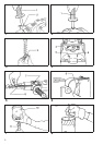
1 Side grip
2 Grip base
3 Tool retainer
4 Change lever
5 For rotation with hammering
6 For hammering only
7 Wing bolt
8 Depth gauge
9 Switch trigger
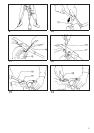
10 Core bit
11 Adapter
12 Center bit
13 Rod
14 Hex wrench
15 Rear cover
16 Screwdriver
17 Brush holder cap
18 Lock nut wrench
19 Crank cap
20 Hammer grease
SPECIFICATIONS
Model HR3520 HR3850
Capacities
Tungsten-carbide bit .............................................................................................. 35 mm 38 mm
Core bit .................................................................................................................. 79 mm 118mm
No load speed (min
–1
) .............................................................................................. 440 240
Blows per min. .......................................................................................................... 3,300 2,900
Overall length ........................................................................................................... 386 mm 430mm
Net weight ................................................................................................................. 6.4 kg 7.5 kg
•
Due to our continuing program of research and
development, the specifications herein are subject
to change without notice.
•
Note: Specifications may differ from country to
country.
Power supply
The tool should be connected only to a power supply
of the same voltage as indicated on the nameplate,
and can be operated on single-phase AC/DC supply.
They are double-insulated in accordance with Euro-
pean Standard and can, therefore, also be used from
sockets without earth wire.
Safety hints
For your own safety, please refer to the enclosed
Safety instructions.
ADDITIONAL SAFETY RULES
1. Wear ahard hat (safety helmet), safety glasses
and/or face shield. It is also highly recom-
mended that you wear a dust mask, ear pro-
tectors and thickly padded gloves.
2. Be sure the bit is secured in place before
operation.
3. Under normal operation, the tool is designed
to produce vibration. The screws can come
loose easily,causing a breakdown oraccident.
Check tightness of screws carefully before
operation.
4. In cold weather or when the tool has not been
used for a long time, let the tool warm up for
several minutes by operating it under no load.
This will loosen up the lubrication. Without
proper warm-up, hammering operation is dif-
ficult.
5. Always be sure you have a firm footing.
Be sure no one is below whenusing the tool in
high locations.
6. Hold the tool firmly with both hands.
7. Keep hands away from moving parts.
8. Do not leave thetool running. Operate the tool
only when hand-held.
9. Do not point the tool at any one in the area
when operating. The bit could fly out and
injure someone seriously.
10. When drilling or chipping into walls, floors or
wherever “live” electrical wires may be
encountered, DO NOT TOUCH ANY METAL
PARTS OF THE TOOL!
Hold the tool by the insulated grasping sur-
faces to prevent electric shock if you drill or
chip into a “live” wire.
11. Do not touch the bit or parts close to the bit
immediately after operation; they may be
extremely hot and could burn your skin.
SAVE THESE INSTRUCTIONS.
OPERATING INSTRUCTIONS
Side grip (auxiliary handle) (Fig.1&2)
For maximum control and saferoperation, always use
the side grip with this tool. The side grip swings
around to either side, allowing easy handling of the
tool in any position. Loosen the side grip by turning it
counterclockwise, swing it to the desired position and
then tighten it by turning clockwise. (Fig. 1)
The side grip can also be installed in the position
shown in Fig. 2. Remove the side grip from the grip
base by turning the sidegrip counterclockwise. Screw
the side grip on either side of the tool, whichever is
convenient.
5