10
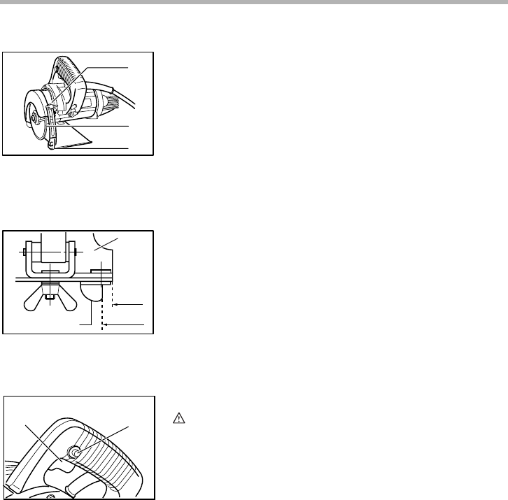
Loosen the wing bolt on the depth guide and move the base
so that the end of the blade case is above the red line on the
depth guide. Then tighten the wing bolt to secure the base.
NOTE:
• If the end of the blade case is under the red line on the
depth guide, the outer flange may hit the workpiece
when you perform the bevel cut.
Sighting
For straight cuts, align the A position on the front of the base
with your cutting line. For 45° bevel cuts, align the B position
with it.
Switch action
CAUTION:
• Before plugging in the tool, always check to see that the
switch trigger actuates properly and returns to the “OFF”
position when released.
To prevent the switch trigger from being accidentally pulled, a
lock-off button is provided.
To start the tool, depress the lock-off button and pull the
switch trigger. Release the switch trigger to stop.
1. Wing bolt
2. End of blade case
3. Red line
1
2
3
003516
1. Base
2. Top guide
A
B
2
1
003520
1. Switch trigger
2. Lock-off button
21
003523


