


8
26. Wear a dust mask and hearing protection when
use the tool.
SAVE THESE INSTRUCTIONS.
WARNING:
MISUSE or failure to follow the safety rules stated in
this instruction manual may cause serious personal
injury.
OPERATING INSTRUCTIONS
Removing or installing saw blade
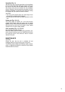
The following blade can be used with this tool.
The thickness of the riving knife is 1.8 mm for Models
5603R and 5703R or 2.0 mm for Model 5903R and
5103R or 2.5 mm for Model 5143R.
CAUTION:
• Do not use saw blades which do not comply with the
characteristics specified in these instructions.
• Do not use saw blades the disc of which is thicker or
the set of which is smaller than the thickness of the riv-
ing knife.
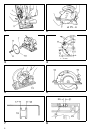
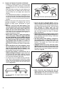
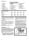
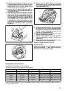
To remove the saw blade, depress the shaft lock fully to
prevent shaft rotation, then use the hex wrench to loosen
the hex socket head bolt. (Fig. 1)
Now remove the outer flange, raise the safety cover as
much as possible, and remove the saw blade. (Fig. 2)
Install the saw blade using the reverse of the removal
procedure. Install the inner flange, saw blade, outer
flange and hex socket head bolt, in that order. Be sure to
secure the hex socket head bolt tightly with the shaft lock
fully depressed. (Fig. 1 & 3)
CAUTION:
• Make sure that the blade teeth point forward in the
same direction as the tool rotation (the arrow on the
blade should point in the same direction as the arrow
on the tool).
• Never depress the shaft lock while the saw is running.
• Use only the Makita socket wrench to remove or install
the blade.
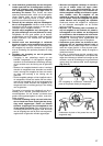
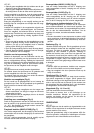
Riving knife adjustment (Fig. 4)
Use the socket wrench to loosen the hex head socket
bolt for the riving knife adjustment, then raise the safety
cover. Move the riving knife up or down over the two pro-
tuberances for settings indicated in the illustration, so as
to obtain the proper clearance between the riving knife
and saw blade.
CAUTION:
Ensure that the riving knife is adjusted such that: The dis-
tance between the riving knife and the toothed rim of the
saw blade is not more than 5 mm. The toothed rim does
not extend more than 5 mm beyond the lower edge of the
riving knife.
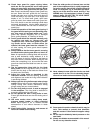
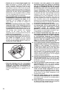
Adjusting depth of cut (Fig. 5)
Loosen the lever on the depth guide and move the base
up or down. At a desired depth of cut, secure the base by
tightening the lever.
CAUTION:
• Use a shallow depth of cut when cutting thin workpiece
for cleaner, safer cuts.
• After adjusting the depth of cut, always tighten the lever
securely.
Adjusting for bevel cuts (Fig. 6)
Loosen the thumb nuts in front and back, and tilt the tool
to the desired angle for bevel cuts (0–45°). Secure the
thumb nuts tightly in front and back after making the
adjustment.
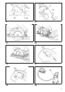
Sighting (5603R, 5703R) (Fig. 7)
For straight cuts, align the right notch on the front of the
base with your cutting line on the workpiece. For 45°
bevel cuts, align the left notch with it.
Top guide (5903R, 5103R) (Fig. 8)
Align your sight line with either the 0° notch for straight
cutting or the 45° notch for 45° angle cuts.
Top guide (5143R) (Fig. 9)
Align your sight line with either the 0° notch for straight
cutting or the 30° notch for 30° angle cuts or the 45°
notch for 45° angle cuts or the 60° notch for 60° angle
cuts.
Switch action (Fig. 10)
To prevent the switch trigger from being accidentally
pulled, a lock-off button is provided. To start the tool,
depress the lock-off button and pull the switch trigger.
Release the switch trigger to stop.
CAUTION:
• Before plugging in the tool, always check to see that
the switch trigger actuates properly and returns to the
“OFF” position when released.
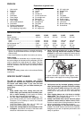
Model Max. dia. Min. dia. Blade thickness Kerf
5603R 165 mm 150 mm Less than 1.7 mm More than 1.9 mm
5703R 190 mm 170 mm Less than 1.7 mm More than 1.9 mm
5903R 235 mm 210 mm Less than 1.9 mm More than 2.1 mm
5103R 270 mm 260 mm Less than 1.8 mm More than 2.2 mm
5143R 355 mm 350 mm Less than 2.3 mm More than 2.7 mm