


5
and slip it into place. Always insert it all the way
until it locks in place with a little click. If not, it may
accidentally fall out of the tool, causing injury to you
or someone around you.
• Do not use force when inserting the battery
cartridge. If the cartridge does not slide in easily, it
is not being inserted correctly.
Switch action
CAUTION:
• Before inserting the battery cartridge into the tool,
always check to see that the switch trigger actuates
properly and returns to the “OFF” position when
released.
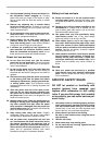
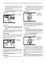
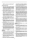
To start the tool, simply pull the switch trigger. Tool speed
is increased by increasing pressure on the switch trigger.
Release the switch trigger to stop.
Electric brake
This tool is equipped with an electric brake. If the tool
consistently fails to quickly stop after switch trigger
release, have tool serviced at a Makita service center.
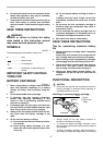
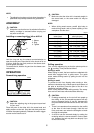
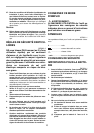
Reversing switch action
This tool has a reversing switch to change the direction of
rotation. Depress the reversing switch lever from the A
side for clockwise rotation or from the B side for counter-
clockwise rotation.
When the reversing switch lever is in the neutral position,
the switch trigger cannot be pulled.
CAUTION:
• Always check the direction of rotation before
operation.
• Use the reversing switch only after the tool comes
to a complete stop. Changing the direction of
rotation before the tool stops may damage the tool.
• When not operating the tool, always set the
reversing switch lever to the neutral position.
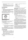
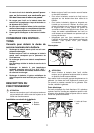
Speed change
To change the speed, first switch off the tool and then
slide the speed change lever to the “2” side for high
speed or “1” side for low speed. Be sure that the speed
change lever is set to the correct position before opera-
tion. Use the right speed for your job.
CAUTION:
• Always set the speed change lever fully to the
correct position. If you operate the tool with the
speed change lever positioned halfway between the
“1” side and “2” side, the tool may be damaged.
• Do not use the speed change lever while the tool is
running. The tool may be damaged.
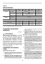
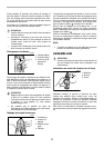
Adjusting the fastening torque
The fastening torque can be adjusted in 17 steps by turn-
ing the adjusting ring so that its graduations are aligned
with the pointer on the tool body. The fastening torque is
minimum when the number 1 is aligned with the pointer,
and maximum when the marking is aligned with the
pointer.
The clutch will slip at various torque levels when set at
the number 1 to 16. The clutch is designed not to slip at
the marking.
Before actual operation, drive a trial screw into your
material or a piece of duplicate material to determine
which torque level is required for a particular application.
1. Switch trigger
1. Reversing
switch lever
1
005218
1
AB
005219
1. Low speed
2. High speed
3. Speed change
lever
1. Graduations
2. Adjusting ring
3. Drill marking
4. Pointer
1
2
3
005220
1
2
3
4
005221