


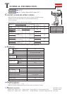

Wiring diagram
P 7/ 7
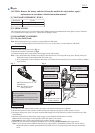
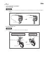
Fig. D-2
Rear view of
Housing set (L)
DC Motor
Switchs’ Lead wires (black, red)
have to be fixed with Lead wire
holder.
DC Motor has to be so
assembled to Housing set (L)
that its Red point mark
is positioned on the back
bone side of the machine.
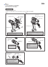
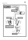
Front side
Battery holder
Switch’s lead
wire (black)
Switch’s lead
wire (red)
Battery holder
Rear side
Housing set (L)
Housing set (R) Side
This protruded Side is fitted
to Housing set (R).
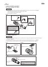
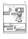
Front side
Rear side
Switch’s Lead
wire (black)
Switch’s Lead
wire (red)
Fig. D-2A.
Red point
mark
Connect Switch’s Lead wire (black) to
Battery holder while facing it to rear side.
Connect Switch’s Lead wire (red) to
Battery holder while facing it to front side.