


11
lever positioned halfway between the “I” side and “II”
side, the tool may be damaged.
• Do not use the speed change lever while the tool is
running. The tool may be damaged.
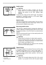
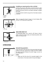
Adjusting the fastening torque
The fastening torque can be adjusted in 17 steps by turning
the adjusting ring so that its graduations are aligned with the
pointer on the tool body. The fastening torque is minimum
when the number 1 is aligned with the pointer, and maximum
when the marking is aligned with the pointer.
The clutch will slip at various torque levels when set at the
number 1 to 16. The clutch is designed not to slip at the
marking.
Before actual operation, drive a trial screw into your material
or a piece of duplicate material to determine which torque
level is required for a particular application.
NOTE:
• The adjusting ring does not lock when the pointer is
positioned only halfway between the graduations.
• Do not operate the tool with the adjusting ring set
between the number 16 and the marking. The tool
may be damaged.
ASSEMBLY
CAUTION:
• Always be sure that the tool is switched off and the
battery cartridge is removed before carrying out any
work on the tool.
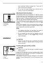
Installing side grip (auxiliary handle)
CAUTION:
• Always be sure that the side grip is installed securely
before operation.
Always use the side grip to ensure operating safety. Install
the side grip so that the teeth on the grip fit in between the
protrusions on the tool barrel.
Then tighten the grip by turning clockwise at the desired
position. It may be swung 360° so as to be secured at any
position.
1. Adjusting ring
2. Graduations
3. Drill marking
4. Pointer
1
2
3
4
002101
1. Grip base
2. Side grip
3. Teeth
4. Protrusions
1
2
3
4
002108