


ENGLISH
Explanation of general view
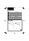
1 Side grip
2 Tighten
3 Chuck key
4 Sleeve
5 Ring
6 High
7 Low
8 Speed control screw
9 Switch trigger
0 Lock button
q Reversing switch lever
w Reversing switch lever
SPECIFICATIONS
Model 6402 DP4700
Capacities
Steel ......................................................................................................... 10 mm 13 mm
Wood ....................................................................................................... 21 mm 36 mm
No load speed (RPM) ................................................................................ 0 – 1,200 0 – 550
Overall length ............................................................................................. 264 mm 275 mm
Net weight .................................................................................................. 1.7 kg 2.0 kg
•
Due to the continuing program of research and
development, the specifications herein are subject
to change without prior notice.
•
Note: Specifications may differ from country to
country.
Power supply
The machine should be connected only to a power
supply of the same voltage as indicated on the
nameplate, andcan onlybe operatedon single-phase
AC supply. They are double-insulated in accordance
with European Standard and can, therefore, also be
used from sockets without earth wire.
Safety hints
For your own safety, please refer to enclosed safety
instructions.
These symbols mean:
Read instruction manual.
DOUBLE INSULATION
ADDITIONAL SAFETY RULES
1. Always be sure you have a firm footing. Be
sure no one is below when using the machine
in high locations.
2. Hold the machine firmly.
3. Keep hands away from rotating parts.
4. When drilling into walls, floors or wherever
‘‘live’’electricalwires maybe encountered,DO
NOT TOUCH ANY METAL PARTS OF THE
MACHINE! Hold the machine by the insulated
grasping surfaces to prevent electric shock if
you drill into a ‘‘live’’ wire.
5. Do notleave the machinerunning. Operatethe
machine only when hand-held.
6. Do not touch the drill bit or the workpiece
immediately after operation; they may be
extremely hot and could burn your skin.
SAVE THESE INSTRUCTIONS.
OPERATING INSTRUCTIONS
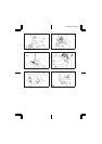
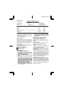
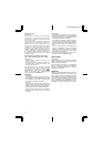
Installing side grip (auxiliary handle) (Fig. 1)
For DP4700 only
Screw the side grip on the machine securely.
Installing or removing drill bit
Important:
Always be sure that the machine is switched off and
unplugged before installing or removing the bit.
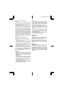
For machines with standard keyed chuck (Fig. 2)
To install the bit, place it in the chuck as far as it will
go. Tightenthe chuck byhand. Place thechuck key in
each ofthe threeholes andtightenclockwise. Besure
to tighten all three chuck holes evenly. To remove the
bit, turn the chuck key counterclockwise in just one
hole, then loosen the chuck by hand.
After using the chuck key, be sure to return it to the
original position.
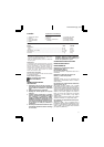
For machines with keyless chuck (Fig. 3)
Hold the ring and turn the sleeve counterciockwise to
open the chuck jaws. Place the bit in the chuck as far
as it will go. Hold the ring firmly and turn the sleeve
clockwise totighten thechuck. To removethe bit,hold
the ring and turn the sleeve counterclockwise.
Switch action (Fig. 4)
CAUTION:
Before plugging in the machine, always check to see
that theswitch triggeractuates properlyandreturns to
the ‘‘OFF’’ position when released.
To start the machine, simply pull the trigger. Machine
speed is increased by increasing pressure on the
trigger. Release the trigger to stop. For continuous
operation, pull the trigger and then push in the lock
button. To stop the machine from the locked position,
pull the trigger fully, then release it. A speed control
screw is provided so that maximum machine speed
can be limited (variable). Turn the speed control
screw clockwise for higher speed, and counterclock-
wise for lower speed.
DP4700/6402 (Eng) (’96. 5. 11)
3