


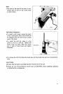
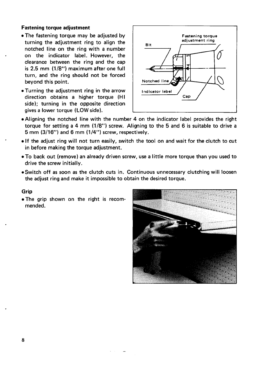
Fastening torque adjustment
I
0
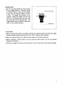
The fastening torque may be adjusted by
turning the adjustment ring to align the
notched line on the ring with
a
number
on the indicator label. However, the
clearance between the ring and the cap
is
2.5
mm
(1/8")
maximum after one full
turn, and the ring should not be forced
beyond this point.
0
Turning the adjustment ring in the arrow
direction obtains
a
higher torque
(HI
side); turning in the opposite direction
gives
a
lower torque
(LOW
side).
Fastening torque
adjustment ring
Bit
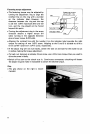
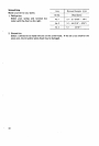
.Aligning the notched line with the number
4
on the indicator label provides the right
torque for setting
a
4
mm
(1/8")
screw. Aligning to the
5
and
6
is
suitable to drive
a
5
mm
(3/16")
and
6
mm
(1/4")
screw, respectively.
0
If
the adjust ring will not turn easily, switch the tool on and wait for the clutch to cut
in before making the torque adjustment.
.To back out (remove) an already driven screw, use
a
little
more torque than you used to
drive the screw initially.
.Switch off
as
soon
as
the clutch cuts in. Continuous unnecessary clutching will loosen
the adjust ring and make
it
impossible to obtain the desired torque.
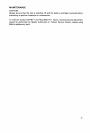
-
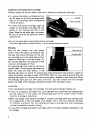
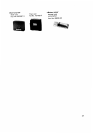
Grip
.The grip
mended.
shown on
the right
is
recom-
8