


4
ENGLISH
Explanation of general view
1 Locking sleeve
2 Approximately 1mm
3 Locator
4 Magnetic socket bit
5 Switch trigger
6 Lock button
7 Reversing switch lever
8Hook
SPECIFICATIONS
Model 6826N
Capacities
Self drilling screw .................................................6mm
No load speed (min
–1
) ..................................... 0– 2,500
Overall length ......................................................282mm
Net weight ............................................................. 1.5kg
• Due to our continuing program of research and devel-
opment, the specifications herein are subject to change
without notice.
• Note: Specifications may differ from country to country.
Intended use
The tool is intended for screw driving in wood, metal and
plastic.
Power supply
The tool should be connected only to a power supply of
the same voltage as indicated on the nameplate, and can
only be operated on single-phase AC supply. They are
double-insulated in accordance with European Standard
and can, therefore, also be used from sockets without
earth wire.
Safety hints
For your own safety, please refer to the enclosed safety
instructions.
ADDITIONAL SAFETY RULES
ENB004-1
1. Hold tool by insulated gripping surfaces when
performing an operation where the cutting tools
may contact hidden wiring or its own cord. Con-
tact with a “live” wire will make exposed metal
parts of the tool “live” and shock the operator.
2. Always be sure you have a firm footing. Be sure
no one is below when using the tool in high loca-
tions.
3. Hold the tool firmly.
4. Keep hands away from rotating parts.
5. Do not touch the bit or the workpiece immedi-
ately after operation; they may be extremely hot
and could burn your skin.
SAVE THESE INSTRUCTIONS.
OPERATING INSTRUCTIONS
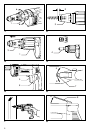
Depth adjustment
The depth can be adjusted by turning the locking sleeve.
Turn it in “A” direction for less depth and in “B” direction
for more depth. One full turn of the locking sleeve equals
1.5mm change in depth. (Fig.1)
Adjust the locking sleeve so that the distance between
the tip of the locator and the screw head is approximately
1mm as shown in Fig.2. Drive a trial screw into your
material or a piece of duplicate material. If the depth is
still not suitable for the screw, continue adjusting until you
obtain the proper depth setting. (Fig. 2)
Removing or installing bit (Fig.3 & 4)
Important:
Always be sure that the tool is switched off and
unplugged before removing or installing the bit.
To remove the magnetic socket bit, first pull the locator
out of the locking sleeve. Then pull the magnetic socket
bit. To install the magnetic socket bit, insert it into the tool
as far as it will go. Then install the locator by pushing it
firmly back onto the locking sleeve.
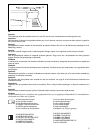
Switch action (Fig. 5)
CAUTION:
Before plugging in the tool, always check to see that the
switch trigger actuates properly and returns to the “OFF”
position when released.
To start the tool, simply pull the trigger. Tool speed is
increased by increasing pressure on the trigger. Release
the trigger to stop. For continuous operation, pull the trig-
ger and then push in the lock button. To stop the tool from
the locked position, pull the trigger fully, then release it.
NOTE:
Even with the switch on and motor running, the bit will not
rotate until you fit the point of the bit in the screw head
and apply forward pressure to engage the clutch.
Reversing switch action (Fig. 6)
CAUTION:
• Always check the direction of rotation before opration.
• Use the reversing switch only after the tool comes to a
complete stop. Changing the direction of rotation
before the tool stops may damage the tool.
This tool has a reversing switch to change the direction of
rotation. Move the reversing switch lever to the “A” side
for clockwise rotation or the “B” side for counterclockwise
rotation.