4
WARNING:
MISUSE or failure to follow the safety rules stated in
this instruction manual may cause serious personal
injury.
USD202-2
Symbols
The followings show the symbols used for tool.
・ volts
・ amperes
・ hertz
・ alternating current
・ no load speed
・ Class II Construction
・ revolutions or reciprocation per minute
・ number of blow
FUNCTIONAL DESCRIPTION
CAUTION:
• Always be sure that the tool is switched off and
unplugged before adjusting or checking function on
the tool.
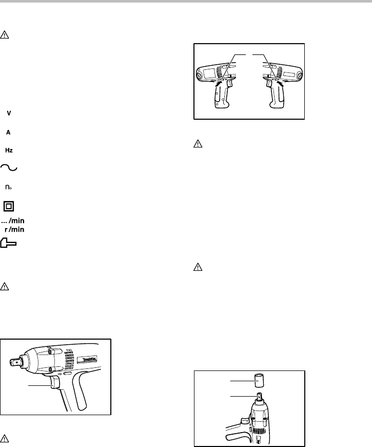
Switch action
1
001642
CAUTION:
• Before plugging in the tool, always check to see
that the switch trigger actuates properly and
returns to the "OFF" position when released.
To start the tool, simply pull the switch trigger. Tool
speed is increased by increasing pressure on the switch
trigger. Release the switch trigger to stop.
Reversing switch action
1
23
45
001643
CAUTION:
• Always check the direction of rotation before
operation.
• Use the reversing switch only after the tool comes
to a complete stop. Changing the direction of
rotation before the tool stops may damage the tool.
This tool has a reversing switch to change the direction
of rotation. Depress the reversing switch lever from the A
side for clockwise rotation or from the B side for
counterclockwise rotation.
ASSEMBLY
CAUTION:
• Always be sure that the tool is switched off and
unplugged before carrying out any work on the
tool.
Selecting correct socket
Always use the correct size socket for bolts and nuts. An
incorrect size socket will result in inaccurate and
inconsistent fastening torque and/or damage to the bolt
or nut.
Installing or removing socket
1
2
001644
To install the socket, push it onto the anvil of the tool until
it locks into place.
To remove the socket, simply pull it off.
Hook
The hook is convenient for temporarily hanging the tool.
This can be removed without using a tool. This can be
installed on either side of the tool.
1. Socket
2. Anvil
1. Reversing
switch lever
2. A side
3. B side
4. Clockwise
5.
Counterclockwise
1. Switch trigger


