


OPERATING INSTRUCTIONS
Installing loop handle
Important:
Always be sure that the tool is switched off and
unplugged before installing the loop handle.
Always install the loop handle on the tool before
operation. Hold the tool’s switch handle and the loop
handle firmly with both hands during operation.
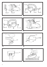
Install the loop handle so that its protrusion will fit into
the matching hole in the gear housing. (Fig. 1)
Install the bolts and tighten them with the hex wrench.
The loop handle can be installed in two different
directions as shown in Fig.2&3, whichever is con-
venient for your work. (Fig.2&3)
Shaft lock (Fig. 4)
Press the shaft lock to prevent spindle rotation when
installing or removing accessories suchas wool pads.
CAUTION:
Never actuate the shaft lock when the spindle is
moving. The tool may be damaged.
Installing or removing wool pad (Fig.1&5)
Important:
Always be sure that the tool is switched off and
unplugged before installing or removing the wool pad.
To install the wool pad, first remove all dirt or foreign
matter from the backing pad. Press the shaft lock and
screw the backing pad onto the spindle. Insert the
sleeve 18 into the center hole of the backing pad.
Using the sleeve 18 as a positioning guide, install the
wool pad on the backing pad with the sleeve 18
inserted throughthe center hole ofthe wool pad.Then
remove the sleeve 18 from the backing pad. To
remove the wool pad, just tear it off the backing pad.
Then unscrew the backing pad while pressing the
shaft lock.
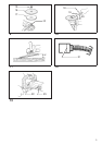
Switch action (Fig. 6)
CAUTION:
Before plugging in the tool, always check to see that
the switch trigger actuates properly and returns to the
‘‘OFF’’ position when released.
To start the tool, simply pull the trigger. Tool speed is
increased by increasing pressure on the trigger.
Release the trigger to stop. For continuous operation,
pull the trigger and then push in the lock button. To
stop the tool from the locked position, pull the trigger
fully, then release it.
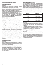
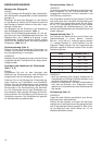
Speed adjusting dial (Fig. 7)
The tool speed can be infinitely adjusted between
600 rpm and 3,000 rpm (rpm at the time when the
switch trigger is fully pulled) by turning the speed
adjusting dial to a given number setting from 1 to 6.
Higher speedis obtained whenthe dial isturned in the
direction of number 6; lower speed is obtained when
it is turned in the direction of number 1. Refer to the
table below for the relationship between the number
settings on the dial and the approximate tool speed.
Number RPM (min
–1
)
1–2 600–900
2 – 3 900 – 1,500
3 – 4 1,500 – 2,100
4 – 5 2,100 – 2,700
5 – 6 2,700 – 3,000
CAUTION:
•
If the tool is operated continuously at low speeds for
a long time, the motor will get overloaded and
heated up.
•
The speed adjusting dial can be turned only as far
as 6 and back to1. Donot forceit past6 or 1, or the
speed adjusting function may no longer work.
Polishing operation (Fig. 8)
CAUTION:
Always wear safety glasses or a face shield during
operation.
Pull the trigger and turn the speed adjusting dial until
you obtain the appropriatespeed for your work. When
polishing, keep the wool pad at an angle of about 15°
to the workpiece surface.
6