


7
ASSEMBLY
CAUTION:
•
Always be sure that the tool is switched off and
unplugged before carrying out any work on the tool.
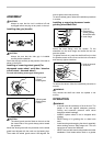
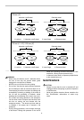
Installing side grip (handle)
005804
CAUTION:
• Always be sure that the side grip is installed
securely before operation.
Screw the side grip securely on the position of the tool as
shown in the figure.
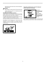
Installing or removing wheel guard (For
depressed center wheel , multi disc / abrasive
cut-off wheel , diamond wheel)
For tool with locking screw type wheel guard
1
2
3
009055
1
2
3
009056
CAUTION:
• The wheel guard must be fitted on the tool so that
the closed side of the guard always points toward
the operator.
Mount the wheel guard with the protrusion on the wheel
guard band aligned with the notch on the bearing box.
Then rotate the wheel guard around 180 degrees. Be
sure to tighten the screw securely.
To remove wheel guard, follow the installation procedure
in reverse.
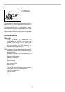
Installing or removing depressed center
grinding wheel/Multi-disc
1
3
2
001070
Mount the inner flange onto the spindle. Fit the
wheel/disc on the inner flange and screw the lock nut
onto the spindle.
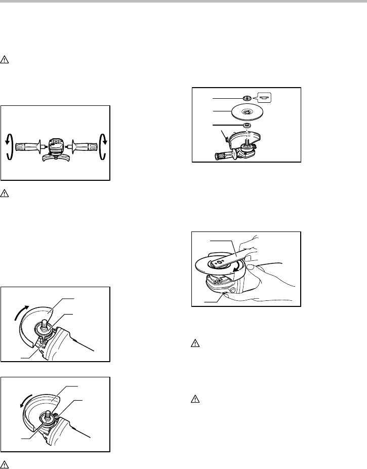
To tighten the lock nut, press the shaft lock firmly so that
the spindle cannot revolve, then use the lock nut wrench
and securely tighten clockwise.
2
1
005917
To remove the wheel, follow the installation procedure in
reverse.
WARNING:
Only actuate the shaft lock when the spindle is not
moving.
OPERATION
WARNING:
• It should never be necessary to force the tool. The
weight of the tool applies adequate pressure.
Forcing and excessive pressure could cause
dangerous wheel breakage.
• ALWAYS replace wheel if tool is dropped while
grinding.
• NEVER bang or hit grinding disc or wheel onto
work.
• Avoid bouncing and snagging the wheel, especially
when working corners, sharp edges etc. This can
cause loss of control and kickback.
• NEVER use tool with wood cutting blades and other
sawblades. Such blades when used on a grinder
1. Lock nut wrench
2. Shaft lock
1. Lock nut
2. Depressed
center grinding
wheel/Multi-disc
3. Inner flange
1. Wheel guard
2. Bearing box
3. Screw
1. Wheel guard
2. Screw
3. Bearing box