


6
• Do not use the speed change lever while the tool is
running. The tool may be damaged.
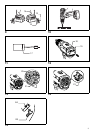
Adjusting the fastening torque (Fig. 6)
The fastening torque can be adjusted in 17 steps by
turning the adjusting ring so that its graduations are
aligned with the pointer on the tool body. The fastening
torque is minimum when the number 1 is aligned with the
pointer, and maximum when the marking is aligned with
the pointer.
The clutch will slip at various torque levels when set at the
number 1 to 16. The clutch is designed not to slip at the
marking.
Before actual operation, drive a trial screw into your
material or a piece of duplicate material to determine
which torque level is required for a particular application.
ASSEMBLY
CAUTION:
• Always be sure that the tool is switched off and the
battery cartridge is removed before carrying out any
work on the tool.
Installing or removing driver bit or drill bit
(Fig. 7)
Turn the sleeve counterclockwise to open the chuck jaws.
Place the bit in the chuck as far as it will go. Turn the
sleeve clockwise to tighten the chuck.
To remove the bit, turn the sleeve counterclockwise.
Installing bit holder (Optional accessory)
(Fig. 8)
Fit the bit holder into the protrusion at the tool foot on
either right or left side and secure it with a screw.
When not using the driver bit, keep it in the bit holders.
Bits 45 mm long can be kept there.
Hook (Optional accessory) (Fig. 9)
The hook is convenient for temporarily hanging the tool.
This can be installed on either side of the tool.
To install the hook, insert it into a groove in the tool
housing on either side and then secure it with a screw.
To remove, loosen the screw and then take it out.
OPERATION
CAUTION:
• Always insert the battery cartridge all the way until it
locks in place. If you can see the red part on the upper
side of the button, it is not locked completely. Insert it
fully until the red part cannot be seen. If not, it may
accidentally fall out of the tool, causing injury to you or
someone around you.
Hold the tool firmly with one hand on the grip and the
other hand on the bottom of the battery cartridge to
control the twisting action.
Screwdriving operation (Fig. 10)
CAUTION:
• Adjust the adjusting ring to the proper torque level for
your work.
Place the point of the driver bit in the screw head and
apply pressure to the tool. Start the tool slowly and then
increase the speed gradually. Release the switch trigger
as soon as the clutch cuts in.
CAUTION:
• Make sure that the driver bit is inserted straight in the
screw head, or the screw and/or bit may be damaged.
NOTE:
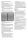
• When driving wood screws, predrill pilot holes to make
driving easier and to prevent splitting of the workpiece.
See the chart.
Drilling operation
First, turn the adjusting ring so that the pointer points to
the marking. Then proceed as follows.
Drilling in wood
When drilling in wood, the best results are obtained with
wood drills equipped with a guide screw. The guide screw
makes drilling easier by pulling the bit into the workpiece.
Drilling in metal
To prevent the bit from slipping when starting a hole,
make an indentation with a center-punch and hammer at
the point to be drilled. Place the point of the bit in the
indentation and start drilling.
Use a cutting lubricant when drilling metals. The
exceptions are iron and brass which should be drilled dry.
CAUTION:
• Pressing excessively on the tool will not speed up the
drilling. In fact, this excessive pressure will only serve
to damage the tip of your bit, decrease the tool
performance and shorten the service life of the tool.
• There is a tremendous force exerted on the tool/bit at
the time of hole break through. Hold the tool firmly and
exert care when the bit begins to break through the
workpiece.
• A stuck bit can be removed simply by setting the
reversing switch to reverse rotation in order to back
out. However, the tool may back out abruptly if you do
not hold it firmly.
• Always secure small workpieces in a vise or similar
hold-down device.
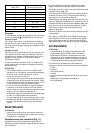
Nominal diameter of wood
screw (mm)
Recommended size of pilot
hole (mm)
3.1 2.0 - 2.2
3.5 2.2 - 2.5
3.8 2.5 - 2.8
4.5 2.9 - 3.2
4.8 3.1 - 3.4
5.1 3.3 - 3.6
5.5 3.7 - 3.9
5.8 4.0 - 4.2
6.1 4.2 - 4.4