


P 14/ 14
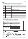
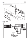
Wiring diagram
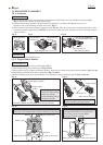
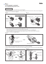
Brush holder
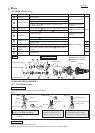
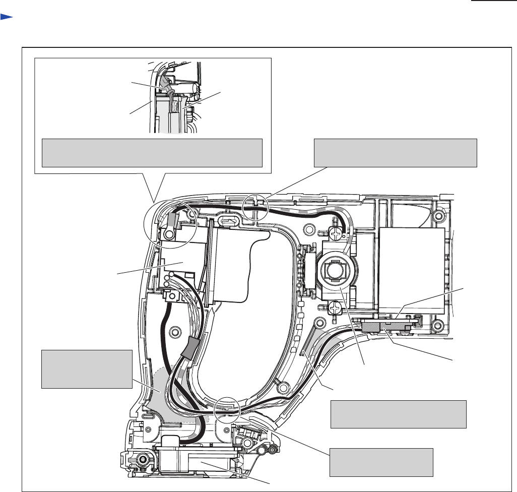
Rib A
Route all of the FET lead wires
on the right side of Rib A.
Terminal
Heat sink
FET
Yoke unit
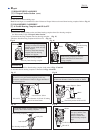
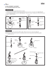
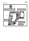
Bend Connecting terminal to Housing set (L) side as
illustrated above.
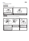
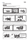
Switch
Fix the Brush holder’s Lead wires
(red and black) with Lead wire holder.
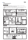
Switch
Put the extra portion
of Lead wires in this
area.
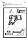
Fix the FET Lead wires
with Lead wire holder.
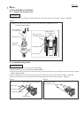
Fig. D-2
Connecting terminal
Housing set (L)