


6
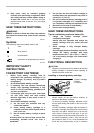
ASSEMBLY
CAUTION:
• Always be sure that the tool is switched off and the
battery cartridge is removed before carrying out
any work on the tool.
Installing or removing the blade
CAUTION:
• Oil on the blade can cause the blade to slip or
come off unexpectedly. Wipe off all excess oil with
a cloth before installing the blade.
• Use caution when handling the blade so that you
are not cut by the sharp edge of the blade teeth.
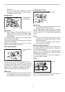
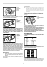
Turn the blade tightening lever clockwise until it hits
against the protrusion on the frame.
4
3
1
2
007150
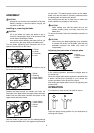
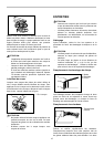
Match the direction of the arrow on the blade to that of
the arrow on the wheels.
1
2
3
4
006192
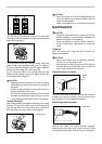
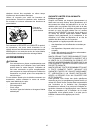
Position the blade around the wheels and insert the
other side of the blade within the upper holder and lower
holder until the blade back contacts the bottom of the
upper holder and lower holder.
1
2
3
4
006193
Hold the blade in place and turn the blade-tightening
lever counterclockwise until it hits against the protrusion
on the frame. This places proper tension on the blade.
Make sure that the blade is correctly positioned within
the blade guard and around the wheels.
Start and stop the tool two or three times to make sure
that the blade runs properly on the wheels.
CAUTION:
• While making sure that the blade runs on the
wheels properly, keep your body away from the
blade area.
To remove the blade, follow the installation procedure in
reverse.
CAUTION:
• When turning the blade tightening lever clockwise
to release the tension on the blade, point the tool
downward because the blade may come off
unexpectedly.
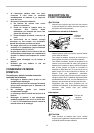
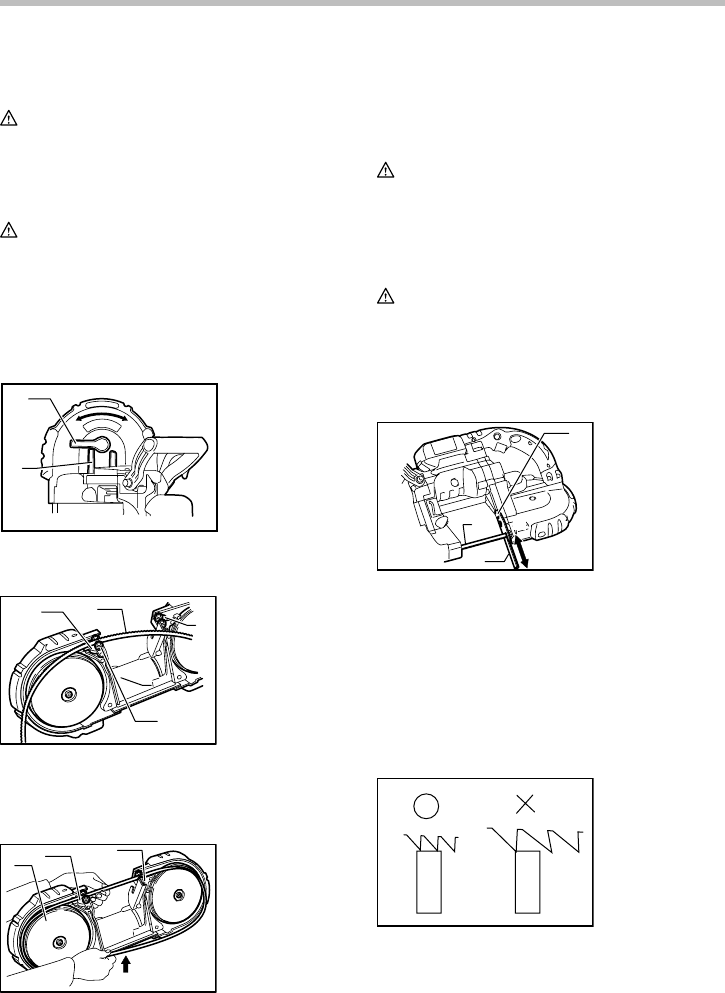
Adjusting the protrusion of stopper plate
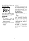
1
3
2
A
B
007151
In the ordinary operation, protrude the stopper plate to
the A side fully.
When the stopper plate strikes against the obstacles like
a wall or the like at the finishing of a cut, loosen two
screws and slide it to the B side in the figure.
After sliding the stopper plate, secure it by tightening two
screws firmly.
OPERATION
It is important to keep at least two teeth in the cut.
007316
Select the proper cutting position for your workpiece by
referring to the figure.
1. Screw
2. Stopper plate
3. Blade
1. Upper holder
2. Lower holder
3. Wheel
4. Press
1. Blade
2. Bearing
3. Upper holder
4. Lower holder
1. Tighten
2. Loosen
3. Protrusion
4. Lever