


(4) After installing the assembled parts in place of Housing L, shift Speed change lever assembly to either low speed
position or high speed position.
(5) Fixing Housing (R) to Housing (L) with six Bind PT3x16 tapping screws.
(6) Insert two Set plates in place. (Fig. 1)
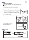
Set Leaf spring in place. (Fig. 8)
Note: Do not face the center edge of Leaf spring to Housing L.
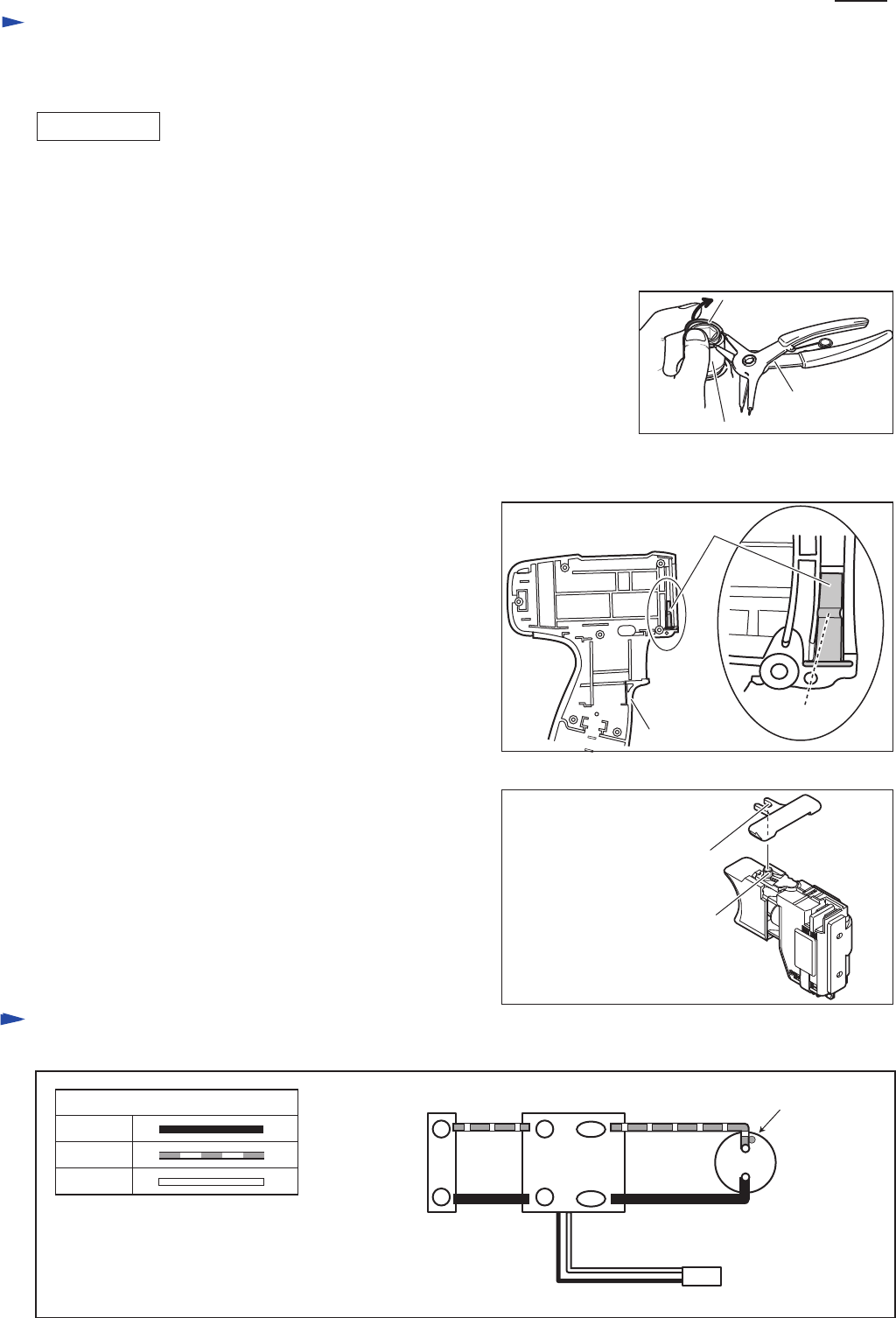
Link the notch of F/R change lever and the protrusion of Switch,
then install them in Housing L. (Fig. 9)
Repair
P 3/ 4
[2] DISASSEMBLY/ASSEMBLY
[3]-1. DC Motor, Gear Assembly, Speed Change Lever Assembly (cont.)
ASSEMBLING
Fig. 9
Fig. 8
Fig. 7
[3]-3. Assembling Leaf Spring
[3]-4. Assembling F/R Change Lever
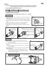
[3]-2. Disassembling Bit Holder of Gear Assembly
Sleeve
Ring spring 10
(1) While pushing the top of sleeve by your thumb to prevent Compression spring 13
from popping out from Bit holder, expand Ring spring 10 using 1R291 and raise
the opposite of the expanded Ring spring 10 by your index finger. (Fig. 7)
(2) Ring spring 10 can be removed.
And Flat washer 11, Compression spring 13, Bit sleeve and Steel ball 3 (2pcs.)
can be removed.
1R291
Leaf spring
center edge
Housing L
notch of F/R change lever
protrusion of Switch
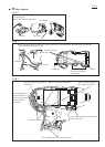
Circuit diagram
Fig. D-1
SwitchTerminal
White
DC motor
red marking
Red
Color index of lead wires' sheath
Black
+ +
- -
M1
M2
LED