


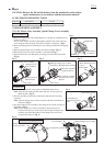
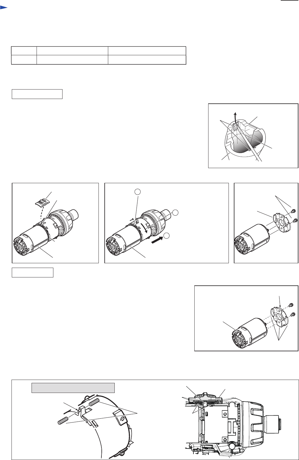
1) Remove two Set plates with which Handles (L) and (R) are assembled to one
another as follows:
Insert a small slotted screwdriver through the punched hole of Set plate and
move Set plate in the direction of the arrow using the screwdriver. (Fig.1)
2) Remove Housing (R) from Housing (L) by loosening six Bind PT3x6 tapping
screws.
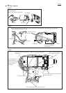
3) Remove Speed change lever assembly from Gear assembly. (Fig. 2)
4) Remove DC motor from Gear assembly as illustrated in Fig. 3
5) Separate DC motor from Bracket by loosening two M3x6 Pan head screws.
(Fig. 4)
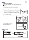
1) Fix Motor bracket to DC motor with two M3x6 Pan head screws.
Note: Align the red marking on DC motor with non-convex portion of
Motor bracket. (Fig. 5)
2) Fix Gear assembly to DC motor with bracket and turn Gear assembly
clockwise.
Note: Align the change lever of Gear assembly with the red marking on
DC motor. (Fig. 3)
3) Fix Speed change lever assembly to the change lever of Gear assembly as
illustrated in Fig. 2.
Note: Set the change lever of Gear assembly in place between two
Compression springs 4 on the reverse side of Speed change lever
assembly, and insert the emboss of the change lever into one of
Compression spring 4. (Fig. 6)
Repair
P 2/ 4
[2] DISASSEMBLY/ASSEMBLY
[3]-1. DC Motor, Gear Assembly, Speed Change Lever Assembly
Fig. 2 Fig. 4Fig. 3
DISASSEMBLING
ASSEMBLING
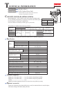
[1] NECESSARY REPAIRING TOOLS
CAUTION: Remove the bit and the battery from the machine for safety before
repair/ maintenance in accordance with the instruction manual!
DescriptionCode No. Use for
1R291 Removing/ Installing Bit sleeve
Fig. 1
Handle (R)
Handle (L)
small slotted
screwdriver
Set plate
(2pcs.)
Retaining ring S and R pliers
Speed change lever assembly
convex portion of
Motor bracket
change lever of
Gear assembly
change lever of
Gear assembly
Emboss of change lever
of Gear assembly
DC motor
Turn Gear assembly
counterclockwise.
Pull out Gear assembly
from DC motor with
Bracket.
DC motor
Motor bracket
M3x6 Pan head screws
(2pcs.)
1
Shift the change lever of Gear
assembly to the high speed position.
2
3
Fig. 5
Fig. 6
non-convex portion
Compression spring 4
Speed change lever assembly
red marking on
terminal of positive
pole
convex portions
Viewed from the upper position