


Wiring diagram (cont.)
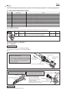
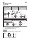
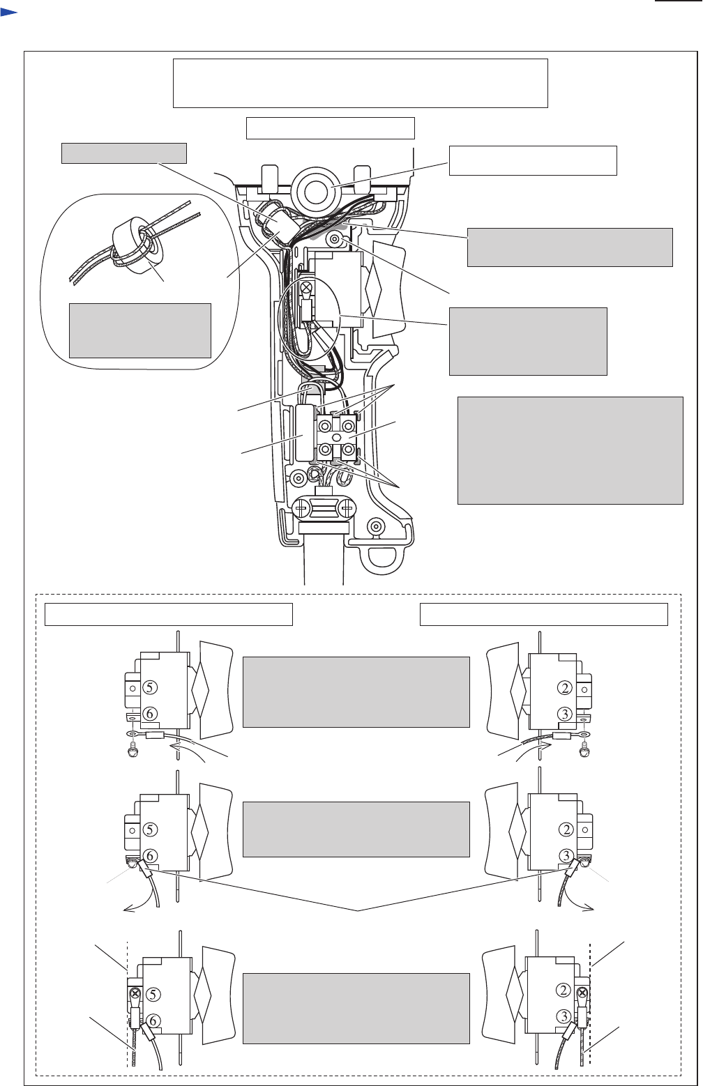
Fig.D-3A
2. Inflect their Insulated connectors of
the Field lead wires until they touch
Screw heads.
3. Insulated connectors of Field lead
wires (purple) and (orange) have to
be located inside of Switch terminal
end.
1. Connect Field lead wire (white) to
Switch terminal No. 6 and Field lead
wire (blue) to Switch terminal No.3
from Switch trigger side.
Field lead
wire (purple)
Field lead wire
(orange)
Field lead wire
(white)
Field lead wire
(blue)
Switch terminal end
Switch terminal end
Screw head
Insulated terminal
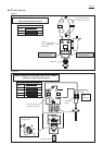
Viewed from Switch cover handle (L) side
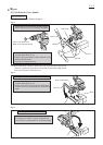
Line filter
Put Line filter here
Boss
Resistor
Rib
Do not to put the folowing Lead wires
on the Ribs and Terminal block.
* Field lead wires (black)
* Noise suppressor’s lead wire (white)
* Lead wires (brown), (blue)
of Power supply cord
Rib
Terminal
block
Noise
supperssor
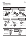
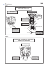
Connect Field lead wires
(white), (purple), (orange),
(blue) as illustrated in
Fig. D-SP.
Coil Field lead wires
(orange) and (purple)
to Line filter one time.
Viewed from Switch cover handle (R) side
Hole for storing Chuck key
Pass field lead wires between Boss
and Hole for storing Chuck key
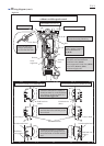
Switch handle cover set (L)
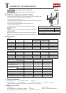
P 8/ 8
Models DS4011 and DS5000 with reverse switch,
without variable speed control
Screw head