


4
WARNING:
MISUSE or failure to follow the safety rules stated in
this instruction manual may cause serious personal
injury.
USD201-2
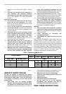
Symbols
The followings show the symbols used for tool.
・ volts
・ amperes
・ hertz
・ alternating current
・ no load speed
・ Class II Construction
・ revolutions or reciprocation per minute
FUNCTIONAL DESCRIPTION
CAUTION:
• Always be sure that the tool is switched off and
unplugged before adjusting or checking function on
the tool.
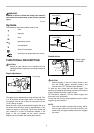
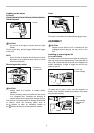
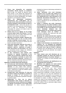
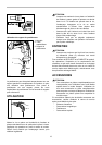
Depth adjustment
1
A
B
009960
The depth can be adjusted by turning the lock ring. Turn
it in "B" direction for less depth and in "A" direction for
more depth. One full turn of the lock ring equals 1.5 mm
(1/16") change in depth.
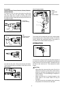
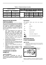
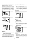
Adjust the lock ring that the distance between the tip of
the locator and the screw head is approximately 1 mm
(3/64") as shown in the figures. Drive a trial screw into
your material or a piece of duplicate material. If the
depth is still not suitable for the screw, continue
adjusting until you obtain the proper depth setting.
1
1mm (3/64")
002619
1
1mm (3/64")
002620
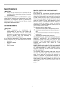
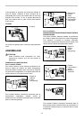
Switch action
1
2
009961
CAUTION:
• Before plugging in the tool, always check to see
that the switch trigger actuates properly and
returns to the "OFF" position when released.
To start the tool, simply pull the switch trigger. Tool
speed is increased by increasing pressure on the switch
trigger. Release the switch trigger to stop.
For continuous operation, pull the switch trigger and
then push in the lock button.
To stop the tool from the locked position, pull the switch
trigger fully, then release it.
NOTE:
• Even with the switch on and motor running, the bit
will not rotate until you fit the point of the bit in the
screw head and apply forward pressure to engage
the clutch.
1. Switch trigger
2. Lock button
1. Locator
1. Locator
1. Lock ring