


P 12/13
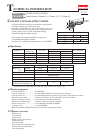
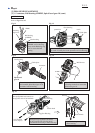
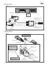
Wiring of Field lead wires
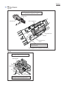
Wiring diagram
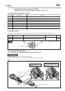
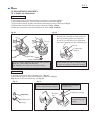
Insert Field into Motor housing so that the Field lead wires (red)
face the opposite side of Switch knob as illustrated below.
Switch
knob side
Switch knob
Switch lever
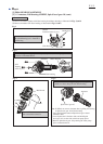
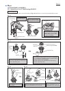
Pull out Field lead wires (red)
from rear opening of the
opposite side of Switch lever.
Field lead wire (red)
Field lead wire (red)
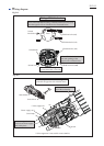
Field lead wire (red)
Field lead wire (red)
Field
Fig. D-3
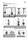
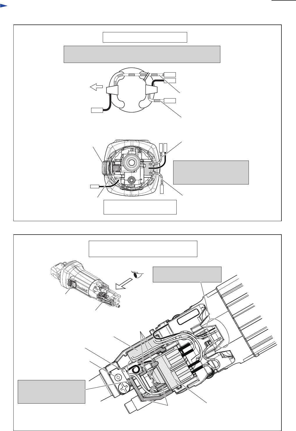
Fig. D-4
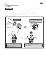
Switch lever
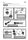
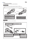
Cord clamp
Put the extra portion of
Lead wire of Power supply
cord in this place.
* Noise suppressor
Switch knob
rib
Field lead wires have to be
tight in Motor housing.
rib
Rear portion of Motor housing
(viewed from opposite side of Switch lever)
Switch
Power supply cord
* Noise suppressor is not used for some countries.
Motor housing
(viewed from Rear cover side)