


P 10/ 14
Repair
[3] DISASSEMBLY/ASSEMBLY
[3] -4. Switch Lever
DISASSEMBLING
(1) Remove Rear cover from Motor housing by removing 4x18 Tapping screw. (Fig. 2)
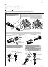
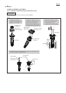
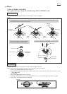
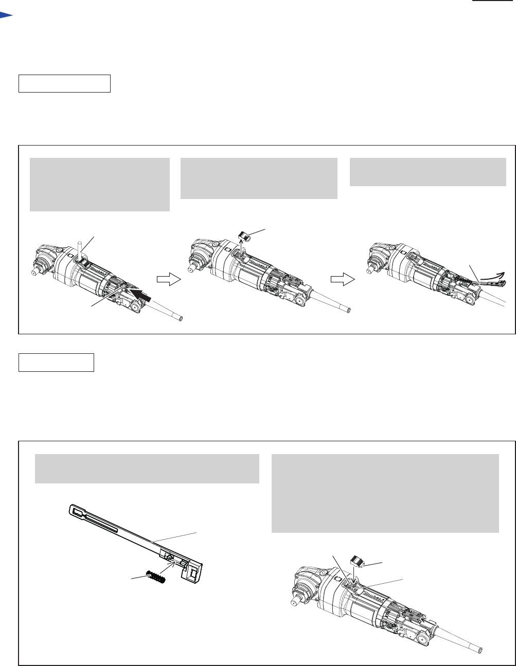
(2) Disassemble Switch lever and Switch knob from the machine as drawn in Fig. 11.
Fig. 11
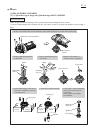
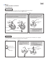
Fig. 12
ASSEMBLING
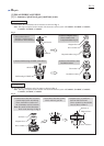
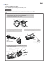
(1) Insert Switch lever into Motor housing. And push it until the loop portion comes into sight through Switch knob
assembling hole on Motor housing. Refer to the right and center illustration in Fig. 11.
(2) Assemble Switch knob to Switch lever as drawn in Fig. 12.
1. Make sure that Compression spring 4 is assembled
to Switch lever in advance.
2. Fitting Switch knob to the loop portion of Switch
lever and the claw portion of Switch plate, hold
Switch knob. And then, release Switch lever.
(The hook of Switch knob interlocks with the hole
of Switch lever when Switch lever is pushed back
to OFF position by Compression spring 4.)
Switch knob
Switch lever
Switch plate
Switch lever
Compression spring 4
3. Bending Switch lever, pull out
Switch lever from Motor housing.
1. While locking Switch knob
with 1R281, strongly push
Switch lever in a direction
designated with black arrow.
2. Switch lever is disconnected from
the locking claw of Switch knob.
Then, remove Switch knob.
1R281
Switch lever
Switch knob
Switch lever