


5
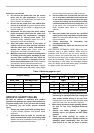
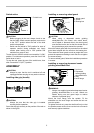
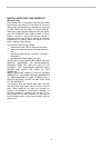
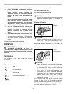
Switch action
1
009423
CAUTION:
• Before plugging in the tool, always check to see
that the slide switch actuates properly and returns
to the "OFF" position when the rear of the slide
switch is depressed.
• Switch can be locked in "ON" position for ease of
operator comfort during extended use. Apply
caution when locking tool in "ON" position and
maintain firm grasp on tool.
To start the tool, slide the switch lever toward the "I (ON)"
position. For continuous operation, press the front of the
switch lever to lock it.
To stop the tool, press the rear of the switch lever, then
slide it toward the "O (OFF)" position.
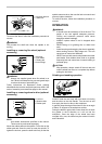
ASSEMBLY
CAUTION:
• Always be sure that the tool is switched off and
unplugged before carrying out any work on the tool.
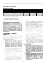
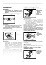
Installing side grip (handle)
009424
CAUTION:
• Always be sure that the side grip is installed
securely before operation.
Screw the side grip securely on the position of the tool as
shown in the figure.
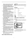
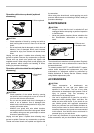
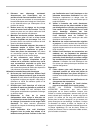
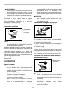
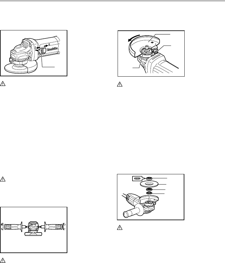
Installing or removing wheel guard
1
2
3
009425
CAUTION:
• When using a depressed center grinding
wheel/Multi-disc, flex wheel, wire wheel brush,
cut-off wheel or diamond wheel, the wheel guard
must be fitted on the tool so that the closed side of
the guard always points toward the operator.
Mount the wheel guard with the protrusion on the wheel
guard band aligned with the notch on the bearing box.
Then rotate the wheel guard to such an angle that it can
protect the operator according to work. Be sure to tighten
the screw securely.
To remove wheel guard, follow the installation procedure
in reverse.
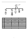
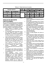
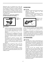
Installing or removing depressed center
grinding wheel/Multi-disc
1
2
3
4
009426
WARNING:
• Always use supplied guard when depressed center
grinding wheel/Multi-disc is on tool. Wheel can
shatter during use and guard helps to reduce
chances of personal injury.
Mount the inner flange onto the spindle. Fit the
wheel/disc on the inner flange and screw the lock nut
onto the spindle.
To tighten the lock nut, press the shaft lock firmly so that
the spindle cannot revolve, then use the lock nut wrench
and securely tighten clockwise.
1. Lock nut
2. Depressed
center grinding
wheel/Multi-disc
3. Ring
4. Inner flange
1. Wheel guard
2. Screw
3. Bearing box
1. Switch lever