


5
CAUTION:
• Before plugging in the tool, always check to see
that the switch trigger actuates properly and
returns to the "OFF" position when released.
• Switch can be locked in "ON" position for ease of
operator comfort during extended use. Apply
caution when locking tool in "ON" position and
maintain firm grasp on tool.
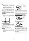
To start the tool, simply pull the switch trigger (in the B
direction). Release the switch trigger to stop. For
continuous operation, pull the switch trigger (in the B
direction) and then push in the lock lever (in the A
direction). To stop the tool from the locked position, pull
the switch trigger fully (in the B direction), then release it.
ASSEMBLY
CAUTION:
•
Always be sure that the tool is switched off and
unplugged before carrying out any work on the tool.
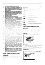
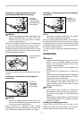
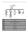
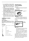
Installing side grip (handle)
006735
CAUTION:
• Always be sure that the side grip is installed
securely before operation.
Screw the side grip securely on the position of the tool
as shown in the figure.
Installing or removing wheel guard
CAUTION:
• When using a depressed center grinding
wheel/Multi-disc, flex wheel or wire wheel brush,
the wheel guard must be fitted on the tool so that
the closed side of the guard always points toward
the operator.
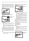
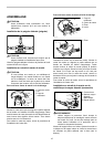
For tool with locking screw type wheel guard
1
2
3
006736
Mount the wheel guard with the protrusion on the wheel
guard band aligned with the notch on the bearing box.
Then rotate the wheel guard around 180 degrees
counterclockwise. Be sure to tighten the screw securely.
To remove wheel guard, follow the installation procedure
in reverse.
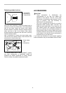
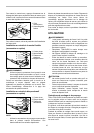
For tool with clamp lever type wheel guard
1
2
3
4
007049
1
007050
Loosen the lever on the wheel guard. Mount the wheel
guard with the protrusion on the wheel guard band
aligned with the notch on the bearing box. Then rotate
the wheel guard around to the position shown in the
figure. Tighten the lever to fasten the wheel guard. If the
lever is too tight or too loose to fasten the wheel guard,
loosen or tighten the nut to adjust the tightening of the
wheel guard band.
To remove wheel guard, follow the installation procedure
in reverse.
1. Nut
1. Bearing box
2. Wheel guard
3. Nut
4. Lever
1. Wheel guard
2. Screw
3. Bearing box