


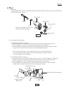
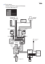
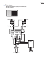
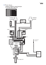
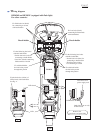
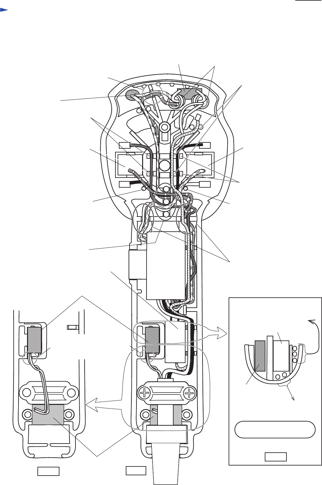
Wiring diagram
P 13 /17
Brush holder
Noise suppressor
Brush holder
Switch
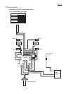
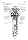
HP2050F and HP2051F (equipped with flash light)
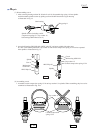
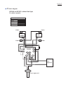
For Europe, High voltage area
* Choke coil
* Noise suppressor
* Insulated terminal
The electrical parts marked with * have to be
set in the illustrated position.
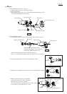
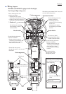
Fix the lead wires passed
through this portion, with
lead holder
Fix with lead holder
the lead wires passed
through this portion
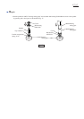
Fix the following lead wires
with this lead holder.
* Switch lead wire (red) for
connecting to brush holder
* Lead wire (black) connecting
field terminals A and B
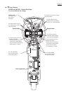
Fix the following lead wires
with this lead holder.
* Switch lead wire (blue) for
connecting to brush holder
* Field lead wire (white)
for connecting to insulated
terminal
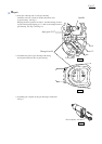
Fix Lead wire (black)
connecting field terminals
A and B, with lead holder.
Fix the following lead wires
with this lead holder.
* Grounding lead wire
(transparent) for connecting
to field core
* Field lead wire (white)
for connecting to insulated
terminal
Fix field lead wire (black)
for connecting to switch,
with lead holder.
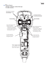
Fix the following lead wires
with this lead holder.
* Switch lead wire (red) for
connecting to insulated terminal
* Choke coil lead wire (orange) for
connecting to insulated terminal
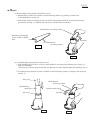
LED circuit
LED
Fix the lead wires (white) of
LED circuit, with lead holder.
See Fig. A.
Fig. A
Fig. B
* Lead wires of power supply cord
* Grounding lead wire (transparent)
for connecting to field core
Lead wire (blue) of LED
circuit
Fig. C
LED circuit
Noise suppressor
Bottom view
(View from cord guard side)