


6
WARNING:
MISUSE or failure to follow the safety rules stated in
this instruction manual may cause serious personal
injury.
OPERATING INSTRUCTIONS
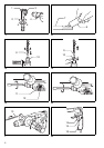
Side grip (auxiliary handle) (Fig. 1)
Always use the side grip to ensure operating safety.
Install the side grip so that the teeth on the grip fit in
between the protrusions on the tool barrel. Then tighten
the grip by turning clockwise at the desired position. It
may be swung 360° so as to be secured at any position.
Installing or removing the bit
CAUTION:
Always be sure that the tool is switched off and
unplugged before installing or removing the bit.
Clean the bit shank and apply bit grease before installing
the bit. (Fig. 2)
Insert the bit into the tool. Turn the bit and push it in until
it engages. (Fig. 3)
After installing, always make sure that the bit is securely
held in place by trying to pull it out.
To remove the bit, pull the chuck cover down all the way
and pull the bit out. (Fig. 4)
Bit angle (when chipping, scaling or demolishing)
CAUTION:
Always be sure that the tool is switched off and
unplugged before changing the bit angle.
The bit can be secured at the desired angle. To change
the bit angle, depress the lock button and rotate the
action mode changing knob to the O symbol. Turn the
bit to the desired angle. (Fig. 5)
Depress the lock button and rotate the action mode
changing knob to the g symbol. Then make sure that
the bit is securely held in place by turning it slightly.
(Fig. 6)
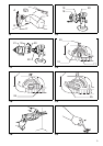
Depth gauge (Fig. 7)
The depth gauge is convenient for drilling holes of uni-
form depth. Loosen the side grip and insert the depth
gauge into the hole in the side grip. Adjust the depth
gauge to the desired depth and tighten the side grip.
NOTE:
The depth gauge cannot be used at the position where
the depth gauge strikes against the gear housing.
Switch action (Fig. 8)
CAUTION:
Before plugging in the tool, always check to see that the
switch trigger actuates properly and returns to the “OFF”
position when released.
To start the tool, simply pull the switch trigger. Tool speed
is increased by increasing pressure on the switch trigger.
Release the switch trigger to stop. For continuous opera-
tion, pull the switch trigger and then push in the lock but-
ton. To stop the tool from the locked position, pull the
switch trigger fully, then release it.
Lighting up the lamps
(Fig. 8)
For model HR2450F, HR2450FT
CAUTION:
Do not look in the light or see the source of light directly.
To turn on the lamp, pull the trigger. Release the trigger
to turn it off.
NOTE:
Use a dry cloth to wipe the dirt off the lens of lamp. Be
careful not to scratch the lens of lamp, or it may lower the
illumination.
Reversing switch action (Fig. 9)
This tool has a reversing switch to change the direction of
rotation. Move the reversing switch lever to the
D
posi-
tion (
A side) for clockwise rotation or the
E
position
(
B side) for counterclockwise rotation.
CAUTION:
• Always check the direction of rotation before operation.
• Use the reversing switch only after the tool comes to a
complete stop. Changing the direction of rotation
before the tool stops may damage the tool.
• When you operate the tool in counterclockwise rotation,
the switch trigger is pulled only halfway and the tool
runs at half speed. For counterclockwise rotation, you
cannot push in the lock button.
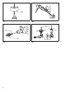
Changing the quick change chuck for SDS-plus
(Fig. 10 & 11)
For model HR2450T/HR2450FT
The quick change chuck for SDS-plus can be easily
exchanged for the quick change drill chuck.
Removing the quick change chuck for SDS-plus
CAUTION:
• Before removing the quick change chuck for SDS-plus,
always remove the bit.
Grasp the change cover of the quick change chuck for
SDS-plus and turn in the direction of the arrow until the
change cover line moves from the symbol to the
symbol. Pull forcefully in the direction of the arrow.
Attaching the quick change drill chuck
Check the line of the quick change drill chuck shows the
symbol. Grasp the change cover of the quick change
drill chuck and set the line to the symbol. Place the
quick change drill chuck on the spindle of the tool.
Grasp the change cover of the quick change drill chuck
and turn the change cover line to the symbol until a
click can clearly be heard.
Selecting action mode
Rotation with hammering (Fig. 12)
For drilling in concrete, masonry, etc., depress the lock
button and rotate the action mode changing knob to the
H symbol. Use a tungsten-carbide tipped bit.
Hammering only (Fig. 13)
For chipping, scaling or demolition operations, depress
the lock button and rotate the action mode changing
knob to the g symbol. Use a bull point, cold chisel, scal-
ing chisel, etc.
Rotation only (Fig. 14)
For drilling in wood, metal or plastic materials, depress
the lock button and rotate the action mode changing
knob to the m symbol. Use a twist drill bit or wood bit.