


4
ENGLISH
Explanation of general view
1 Side grip
2Grip base
3 Red dot (Tool holder)
4 Red dot (Tool retainer)
5 Tool retainer
6 Press in
7 Turn 180°
8 Change lever
9 For rotation with hammering
10 For hammering only
11 Wing bolt
12 Depth gauge
13 Switch trigger
14 Core bit
15 Adapter
16 Center bit
17 Rod
18 Hex wrench
19 Rear cover
20 Screwdriver
21 Brush holder cap
22 Lock nut wrench
23 Crank cap
24 Hammer grease
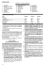
SPECIFICATIONS
Model HR3520B HR3850B HR3850K
Capacities
Tungsten-carbide bit ................................................................. 35 mm 38 mm 38 mm
Core bit ..................................................................................... 79 mm 118 mm 118 mm
No load speed (min
–1
) ................................................................. 440 240 240
Blows per min. ............................................................................. 3,300 2,900 2,900
Overall length .............................................................................. 400 mm 442 mm 455 mm
Net weight ................................................................................... 5.8 kg 7.5 kg 7.5 kg
• Due to our continuing program of research and devel-
opment, the specifications herein are subject to change
without notice.
• Note: Specifications may differ from country to country.
Power supply
The tool should be connected only to a power supply of
the same voltage as indicated on the nameplate, and can
be operated on single-phase AC/DC supply. They are
double-insulated in accordance with European Standard
and can, therefore, also be used from sockets without
earth wire.
Safety hints
For your own safety, please refer to the enclosed Safety
instructions.
SPECIFIC SAFETY RULES
GEB007-2
DO NOT let comfort or familiarity with product
(gained from repeated use) replace strict adherence
to rotary hammer safety rules. If you use this tool
unsafely or incorrectly, you can suffer serious per-
sonal injury.
1. Wear ear protectors. Exposure to noise can cause
hearing loss.
2. Use auxiliary handles supplied with the tool.
Loss of control can cause personal injury.
3. Hold power tools by insulated gripping surfaces
when performing an operation where the cutting
tool may contact hidden wiring or its own cord.
Contact with a “live” wire will make exposed metal
parts of the tool “live” and shock the operator.
4. Wear a hard hat (safety helmet), safety glasses
and/or face shield. Ordinary eye or sun glasses
are NOT safety glasses. It is also highly recom-
mended that you wear a dust mask and thickly
padded gloves.
5. Be sure the bit is secured in place before opera-
tion.
6. Under normal operation, the tool is designed to
produce vibration. The screws can come loose
easily, causing a breakdown or accident. Check
tightness of screws carefully before operation.
7. In cold weather or when the tool has not been
used for a long time, let the tool warm up for a
while by operating it under no load. This will
loosen up the lubrication. Without proper warm-
up, hammering operation is difficult.
8. Always be sure you have a firm footing.
Be sure no one is below when using the tool in
high locations.
9. Hold the tool firmly with both hands.
10. Keep hands away from moving parts.
11. Do not leave the tool running. Operate the tool
only when hand-held.
12. Do not point the tool at any one in the area when
operating. The bit could fly out and injure some-
one seriously.
13. Do not touch the bit or parts close to the bit
immediately after operation; they may be
extremely hot and could burn your skin.
14. Some material contains chemicals which may be
toxic. Take caution to prevent dust inhalation
and skin contact. Follow material supplier safety
data.
SAVE THESE INSTRUCTIONS.
WARNING:
MISUSE or failure to follow the safety rules stated in
this instruction manual may cause serious personal
injury.
OPERATING INSTRUCTIONS
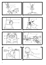
Side grip (auxiliary handle) (Fig. 1 & 2)
For maximum control and safer operation, always use the
side grip with this tool. The side grip swings around to
either side, allowing easy handling of the tool in any posi-
tion. Loosen the side grip by turning it counterclockwise,
swing it to the desired position and then tighten it by turn-
ing clockwise. (Fig. 1)
The side grip can also be installed in the position shown
in Fig. 2. Remove the side grip from the grip base by
turning the side grip counterclockwise. Screw the side
grip on either side of the tool, whichever is convenient.