


4
GEB028-2
NIBBLER SAFETY WARNINGS
1. Hold the tool firmly.
2. Secure the workpiece firmly.
3. Keep hands away from moving parts.
4. Edges and chips of the workpiece are sharp.
Wear gloves. It is also recommended that you
put on thickly bottomed shoes to prevent
injury.
5. Do not put the tool on the chips of the
workpiece. Otherwise it can cause damage
and trouble on the tool.
6. Do not leave the tool running. Operate the tool
only when hand-held.
7. Always be sure you have a firm footing.
Be sure no one is below when using the tool
in high locations.
8. Do not touch the punch, die or the workpiece
immediately after operation; they may be
extremely hot and could burn your skin.
9. Avoid cutting electrical wires. It can cause
serious accident by electric shock.
SAVE THESE INSTRUCTIONS.
WARNING:
DO NOT let comfort or familiarity with product
(gained from repeated use) replace strict adherence
to safety rules for the subject product. MISUSE or
failure to follow the safety rules stated in this
instruction manual may cause serious personal
injury.
USD201-2
Symbols
The followings show the symbols used for tool.
・ volts
・ amperes
・ hertz
・ alternating current
・ no load speed
・ Class II Construction
・ revolutions or reciprocation per minute
FUNCTIONAL DESCRIPTION
CAUTION:
• Always be sure that the tool is switched off and
unplugged before adjusting or checking function
on the tool.
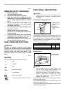
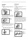
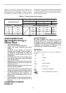
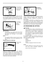
Permissible cutting thickness
1
2
013355
The thickness of material to be cut depends upon the
tensile strength of the material itself. The groove on the
die holder acts as a thickness gauge for allowable
cutting thickness. Do not attempt to cut any material
which will not fit into this groove.
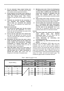
Max.cutting capacities mm ga
Steel up to 400 N/mm
2
3.2 10
Steel up to 600 N/mm
2
2.5 13
Steel up to 800 N/mm
2
1.0 20
Aluminum up to 200 N/mm
2
3.5 10
006439
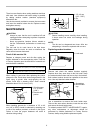
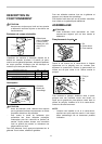
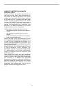
Switch action
12
013356
CAUTION:
• Before plugging in the tool, always check to see
that the switch trigger actuates properly and
returns to the "OFF" position when released.
• Switch can be locked in "ON" position for ease of
operator comfort during extended use. Apply
caution when locking tool in "ON" position and
maintain firm grasp on tool.
To start the tool, simply pull the switch trigger. Release
the switch trigger to stop.
For continuous operation, pull the switch trigger and
then push in the lock button.
To stop the tool from the locked position, pull the switch
trigger fully, then release it.
1. Switch trigger
2. Lock button
1. Stainless steel
gauge 2.5 mm
(3/32")
2. Mild steel
gauge 3.2 mm
(1/8")