


22. Be alert at all times, especially during repeti-
tive, monotonous operations. Don’t be lulled
into a false sense of security. Blades are
extremely unforgiving.
23. Always use accessories recommended in
Makita catalog. Use of improper accessories
such as abrasive wheels may cause an injury.
24. Don’t abuse cord. Never yank cord to discon-
nect it from the receptacle. Keep cord away
from heat, oil, water and sharp edges.
25. Do not use the saw to cut other than alumi-
num, wood or similar materials.
26. Connectmiter saws toa dust collectingdevice
when sawing.
27. Select saw blades in relation to the material to
be cut.
28. Take care when slotting.
29. Replace the kerf board when worn.
SAVE THESE INSTRUCTIONS.
OPERATING INSTRUCTIONS
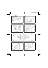
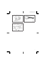
Bench mounting miter saw (Fig. 1)
This machine should be bolted with two bolts to a
level and stable surface using the bolt holes provided
in the machine’s base. This will help prevent tipping
and possible injury.
Removing or installing saw blade
Important:
Always be sure that the machine is switched off and
unplugged before removing or installing the blade.
To remove theblade, use the socketwrench to loosen
the hex bolt holding the center cover by turning it
more than three turns counterclockwise. Raise the
safety cover and center cover. (Fig. 2)
Press the shaft lock so that the blade cannot revolve
and use the socket wrench to loosen the hex bolt
clockwise. Then remove the hex bolt, flange and
blade. (Fig. 3)
To install the blade, mount the blade onto the spindle,
making sure that the direction of the arrow on the
surface of the blade matches the direction of the
arrow on the blade case. (Fig. 4)
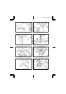
CAUTION: (Fig 5)
For machines with silver ring factory-installed
between flanges
The silver ringwith 25.4 mm outer diameteris factory-
installed between the flanges. The black ring with
25 mm outer diameter is included as standard equip-
ment. Before mounting the blade onto the spindle,
always be sure that the correct ring for the arbor hole
of the blade you intend to use is installed onto the
spindle.
For machines with black ring factory-installed
between flanges
The black ring with 25 mm outer diameter is factory-
installed between flanges.
For machines with no ring factory-installed
between flanges
The black ring with 25 mm outer diameter is included
as standard equipment. When using a blade with
25 mm hole diameter, install this ring between
flanges.
Install the flange and hex bolt, and then use the
socket wrench to tighten the hex bolt securely coun-
terclockwise while pressing the shaft lock. Then
tighten the hex bolt clockwise to secure the center
cover.
CAUTION:
Use only the Makita socket wrench provided to install
or remove the blade. Failure to do so may result in
overtightening orinsufficient tighteningof the hexbolt.
This could cause an injury.
Safety cover (Fig. 6)
When lowering the handle, the safety cover rises
automatically.The cover returns to itsoriginal position
when the cut is completed and the handle is raised.
NEVER DEFEAT OR REMOVE THE SAFETY
COVER. In the interest of your personal safety,
always maintain the safety cover in good condition.
Any irregular operation of the safety cover should be
corrected immediately. NEVER USE THE MACHINE
WITHA FAULTY SAFETYCOVER. If the see-through
safety cover becomes dirty, or sawdust adheres to it
in such a way that the blade and/or workpiece is no
longer easily visible, unplug the saw and clean the
cover carefully witha damp cloth. Do notuse solvents
or any petroleum-based cleanerson the plastic cover.
Dust bag (Fig.7&8)
The use of the dust bag makes cutting operations
clean and dustcollection easy. To attachthe dust bag,
insert the elbow into the dust spout on the blade case
and fit the bag’s entry port over the elbow.
When the dust bag is about half full, remove the dust
bag from the machine and pull the fastener out.
Empty the dust bagof its contents, tapping it lightlyso
as to remove particles adhering to the insides which
might hamper further collection.
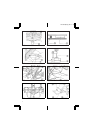
Switch action
CAUTION:
Before plugging in the machine, always check to see
that theswitch trigger actuatesproperly and returnsto
the ‘‘OFF’’ position when released.
For machines without lever (Fig. 9)
To start the machine, simply pull the trigger. Release
the trigger to stop.
For machines with lever (Fig. 10)
To prevent the trigger from being accidentally pulled,
a lock-off button is provided. To start the machine,
press the lever at the side of the handle. The lock-off
button is pressed in by the lever. Thenpull the trigger.
Release the trigger to stop.
LS1030 (E) (’98. 10. 21)
7