


13
001774
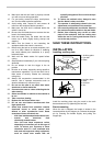
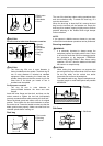
CAUTION:
• Always secure all moving portions before carrying
the tool.
• Stopper pin is for carrying and storage purposes
only and not for any cutting operations.
MAINTENANCE
CAUTION:
• Always be sure that the tool is switched off and
unplugged before attempting to perform inspection
or maintenance.
WARNING:
• Always be sure that the blade is sharp and clean
for the best and safest performance.
Adjusting the cutting angle
This tool is carefully adjusted and aligned at the factory,
but rough handling may have affected the alignment. If
your tool is not aligned properly, perform the following:
1. Miter angle
1
002258
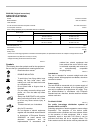
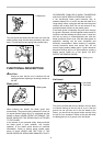
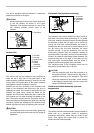
Loosen the grip which secures the turn base. Turn
the turn base so that the pointer points to 0° on the
miter scale. Tighten the grip and loosen the hex
bolts securing the guide fence using the socket
wrench.
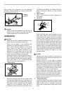
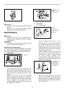
Lower the handle fully and lock it in the lowered
position by pushing in the stopper pin. Square the
side of the blade with the face of the guide fence
using a triangular rule, try-square, etc. Then
securely tighten the hex bolts on the guide fence in
the order from the right side.
3
1
2
002259
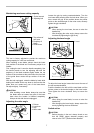
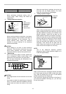
2. Bevel angle
(1) 0° bevel angle
2
4
3
1
001768
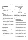
Lower the handle fully and lock it in the
lowered position by pushing in the stopper
pin. Loosen the lever at the rear of the tool.
Loosen the hex nut and turn the 0° bevel
angle adjusting bolt on the right side of the
turn base two or three revolutions clockwise
to tilt the blade to the right.
Carefully square the side of the blade with
the top surface of the turn base using the
triangular rule, try-square, etc. by turning the
0° bevel angle adjusting bolt
counterclockwise. Then tighten the hex nut to
secure the 0° bevel angle adjusting bolt and
tighten the lever securely.
1
2
3
001819
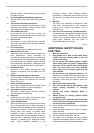
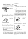
Make sure that the pointer on the turn base
point to 0° on the bevel scale on the arm. If it
does not point to 0°, loosen the screw which
secures the pointer and adjust the pointer so
that it will point to 0°.
1. Triangular rule
2. Saw blade
3. Top surface of
turn base
1. Arm
2. Lever
3. 0 ゚ adjusting
bolt
4. Hex nut
1. Triangular rule
2. Grip
3. Guide fence
1. Hex bolt