


8
1
2
3
4
009518
2
1
3
009737
1
009736
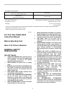
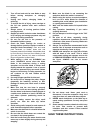
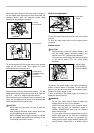
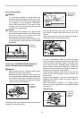
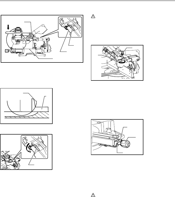
First, unplug the tool. Lower the stopper lever to position
the saw blade as shown in the figure. Push the carriage
toward the guide fence fully and lower the handle
completely. Use the socket wrench to turn the adjusting
bolt until the periphery of the blade extends slightly
below the top surface of the turn base at the point where
the front face of the guide fence meets the top surface of
the turn base.
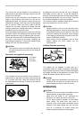
With the tool unplugged, rotate the blade by hand while
holding the handle all the way down to be sure that the
blade does not contact any part of the lower base.
Re-adjust slightly, if necessary.
After adjustment, always return the stopper lever to the
original position by turning it counterclockwise.
CAUTION:
• After installing a new blade, always be sure that
the blade does not contact any part of the lower
base when the handle is lowered completely.
Always do this with the tool unplugged.
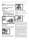
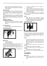
Stopper arm
1
2
009487
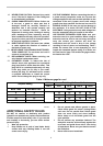
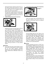
The lower limit position of the blade can be easily
adjusted with the stopper arm. To adjust it, rotate the
stopper arm in the direction of the arrow as shown in the
figure. Adjust the adjusting screw so that the blade stops
at the desired position when lowering the handle fully.
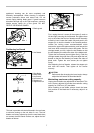
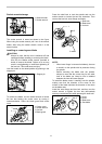
Adjusting the miter angle
1
2
3
009517
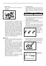
Push the grip so that the cams engages and turn it
clockwise until it stops. Turn the turn base while pressing
down the lock lever. When you have moved the grip to
the position where the pointer points to the desired angle
on the miter scale, turn the grip to 90° counterclockwise
to lock the turn base.
CAUTION:
• When turning the turn base, be sure to raise the
handle fully.
• After changing the miter angle, always secure the
turn base by turning the grip to 90°
counterclockwise.
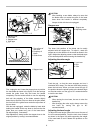
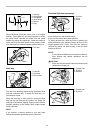
Adjusting the bevel angle
To adjust the bevel angle, loosen the lever at the rear of
the tool counterclockwise. Push the latch lever forward
as shown in the figure fully while supporting the weight
of the saw head so as to release the pressure on the
lock pin.
1. Lock lever
2. Grip
3. Cam
1. Stopper arm
2. Adjusting screw
1. Stopper lever
1. Top surface of
turn base
2. Periphery of
blade
3. Guide fence
1. Adjusting bolt
2. Turn base
3. Stopper lever
4. Slide pipe