


6
WARNING:
• For your safety, this tool is equipped with lock-off
lever which prevents the tool from unintended
starting. NEVER use the tool if it runs when you
simply pull the switch trigger without pressing the
lock-off lever. Return tool a MAKITA service center
for proper repairs BEFORE further usage.
• NEVER tape down or defeat purpose and function
of lock-off lever.
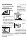
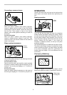
To prevent the switch trigger from being accidentally
pulled, a lock-off button is provided.
To start the tool, depress the lock-off button and pull the
switch trigger. Release the switch trigger to stop.
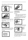
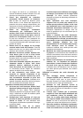
Foot
1
2
3
011739
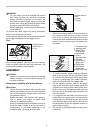
After a cutting operation, raise the back side of the tool
and a foot comes under the level of the rear base. This
prevents the tool blades to be damaged.
ASSEMBLY
CAUTION:
• Always be sure that the tool is switched off and the
battery cartridge is removed before carrying out
any work on the tool.
Removing or installing mini planer blades
CAUTION:
• Tighten the blade installation bolts carefully when
attaching the blades to the tool. A loose installation
bolt can be dangerous. Always check to see they
are tightened securely.
• Handle the blades very carefully. Use gloves or
rags to protect your fingers or hands when
removing or installing the blades.
• Use only the Makita wrench provided to remove or
install the blades. Failure to do so may result in
overtightening or insufficient tightening of the
installation bolts. This could cause an injury.
1
2
4
3
011740
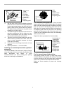
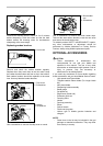
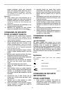
1. Remove the existing blade, if the tool has been in
use, carefully clean the drum surfaces and the
drum cover. To remove the blades on the drum,
unscrew the three installation bolts with the socket
wrench. The drum cover comes off together with
the blades.
1
2
3
4
5
6
7
8
9
10
002565
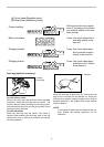
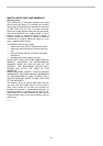
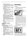
2. To install the blades, loosely attach the adjusting
plate to the set plate with the pan head screws
and set the mini planer blade on the gauge base
so that the cutting edge of the blade is perfectly
flush with the inside flank of the gauge plate.
3. Set the adjusting plate/set plate on the gauge
base so that the planer blade locating lugs on the
set plate rest in the mini planer blade groove, then
press in the heel of the adjusting plate flush with
the back side of the gauge base and tighten the
pan head screws.
4. It is important that the blade sits flush with the
inside flank of the gauge plate, the planer blade
locating lugs sit in the blade groove and the heel
of the adjusting plate is flush with the back side of
the gauge base. Check this alignment carefully to
ensure uniform cutting.
5. Slip the heel of the adjusting plate into the groove
of the drum.
1. Pan head screw
2. Adjusting plate
3. Planer blade
locating lugs
4. Gauge plate
5. Heel of
adjusting plate
6. Set plate
7. Inside flank of
gauge plate
8. Gauge base
9. Back side of
gauge base
10.
Mini planer blade
1. Socket wrench
2. Bolt
3. Loosen
4. Tighten
1. Planer blade
2. Rear base
3. Foot