


5
CAUTION:
• Since excessive cutting may cause overload of the
motor or difficulty in controlling the tool, the depth
of cut should not be more than 15 mm (9/16") at a
pass when cutting grooves with an 8 mm (5/16")
diameter bit.
• When cutting grooves with a 20 mm (13/16")
diameter bit, the depth of cut should not be more
than 5 mm (3/16") at a pass.
When you wish to cut grooves more than 15 mm
(9/16") deep with an 8 mm (5/16") diameter bit or
more than 5 mm (3/16") deep with a 20 mm
(13/16") diameter bit, make several passes with
progressively deeper bit settings.
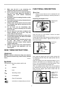
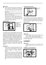
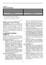
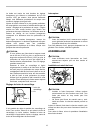
Stopper block
1
2
3
4
5
009746
The stopper block has three adjusting hex bolts which
raise or lower 0.8 mm (about 1/32") per turn. You can
easily obtain three different depths of cut using these
adjusting hex bolts without readjusting the stopper pole.
Adjust the lowest hex bolt to obtain the deepest depth of
cut, following the method of "Adjusting depth of cut".
Adjust the two remaining hex bolts to obtain shallower
depths of cut. The differences in height of these hex
bolts are equal to the differences in depths of cut.
To adjust the hex bolts, turn the hex bolts. The stopper
block is also convenient for making three passes with
progressively deeper bit settings when cutting deep
grooves.
CAUTION:
• When using a bit having total length of 60 mm
(2-3/8") or more, or edge length of 35 mm (1-3/8")
or more, the depth of cut cannot be adjusted as
previously mentioned. To adjust, proceed as
follows:
Loosen the lock lever and carefully adjust bit
protrusion below the tool base to the desired depth
of cut by moving the tool body up or down. Then
retighten the lock lever to lock the tool body at that
depth of cut. Keep the tool body locked at this
position during use. Since the bit always protrudes
from the tool base, be careful when handling the
tool.
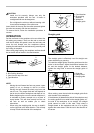
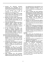
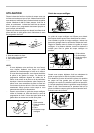
Adjusting the lock lever
1
2
009745
The locked position of the lock lever is adjustable. To
adjust it, remove the screw securing the lock lever. The
lock lever will come off. Set the lock lever at the desired
angle. After adjustment, tighten the lock lever clockwise.
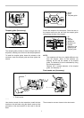
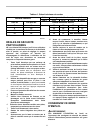
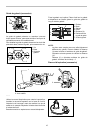
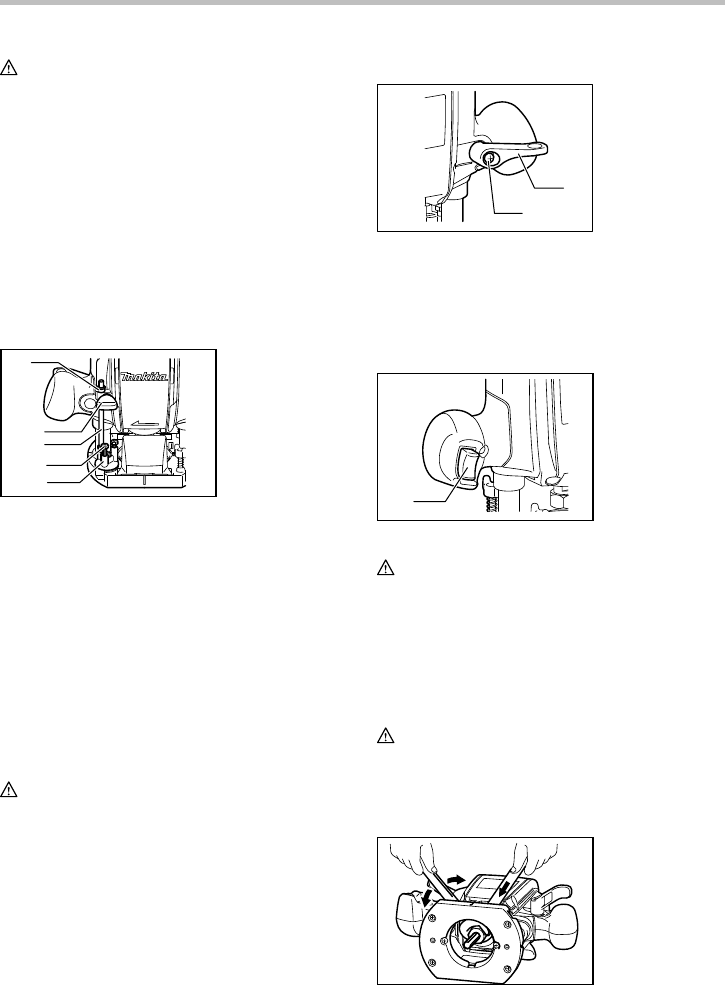
Switch action
1
009747
CAUTION:
• Before plugging in the tool, always check to see
that the switch trigger actuates properly and
returns to the "OFF" position when released.
To start the tool, simply pull the switch trigger. Release
the switch trigger to stop.
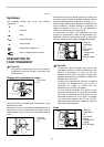
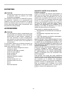
ASSEMBLY
CAUTION:
• Always be sure that the tool is switched off and
unplugged before carrying out any work on the
tool.
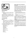
Installing or removing the bit
009748
1. Switch trigger
1. Lock lever
2. Screw
1. Depth pointer
2. Screw
3. Stopper pole
4. Adjusting hex
bolt
5. Stopper block