


9
• Guard assembly
Part No. 191214-3 ... For 180 mm (7”)
Part No. 191215-1 ... For 230 mm (9”)
Guard accessory kit
Part No. 191228-2 ... For 180 mm (7”)
Part No. 191231-3 ... For 230 mm (9”)
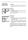
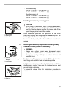
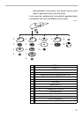
Installing or removing wheel guard
CAUTION:
• When using a depressed center grinding wheel/Multi-
disc, flex wheel or wire wheel brush, the wheel guard
must be fitted on the tool so that the closed side of the
guard always points toward the operator.
Mount the wheel guard with the protrusion on the wheel
guard band aligned with the groove on the bearing box. Be
sure to tighten both screws securely.
To remove wheel guard, follow the installation procedure in
reverse.
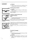
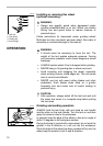
Installing or removing depressed center grinding
wheel/Multi-disc (optional accessory)
WARNING:
• Always use optional guard when depressed center
grinding wheel/Multi-disc is on tool. Wheel can shatter
during use and guard helps to reduce chances of
personal injury.
Mount the inner flange onto the spindle. Fit the wheel on the
inner flange and screw the lock nut onto the spindle.
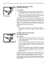
To tighten the lock nut, press the shaft lock firmly so that the
spindle cannot revolve, then use the lock nut wrench and
securely tighten clockwise.
To remove the wheel, follow the installation procedure in
reverse.
1. Wheel guard
2. Bearing box
3. Screw
1
23
001066
1. Lock nut
2. Depressed center grinding wheel/
Multi-disc
3. Inner flange
1
2
3
001078
1. Lock nut wrench
2. Shaft lock
1
2
001091