


9
Installing or removing wheel guard
(For depressed center wheel, multi disc /
abrasive cut-off wheel, diamond wheel)
WARNING:
• When using a depressed center grinding
wheel/Multi-disc, wire wheel brush, cut-off wheel
or diamond wheel, the wheel guard must be fitted
on the tool so that the closed side of the guard
always points toward the operator.
• When using an abrasive cut-off / diamond wheel,
be sure to use only the special wheel guard
designed for use with cut-off wheels.
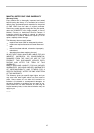
For tool with clamp lever type wheel guard
1
2
3
4
015084
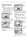
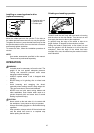
Loosen the lever on the wheel guard after loosening the
screw. Mount the wheel guard with the protrusion on the
wheel guard band aligned with the notch on the bearing
box. Then rotate the wheel guard to such an angle that
it can protect the operator according to work.
1
2
3
015085
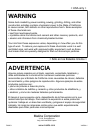
Tighten the lever to fasten the wheel guard. If the lever
is too tight or too loose to fasten the wheel guard,
loosen or tighten the screw to adjust the tightening of
the wheel guard band.
To remove wheel guard, follow the installation
procedure in reverse.
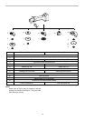
For tool with locking screw type wheel guard
1
2
3
015303
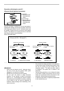
Mount the wheel guard with the protrusions on the
wheel guard band aligned with the notches on the
bearing box. Then rotate the wheel guard around 180゚
counterclockwise. Be sure to tighten the screw securely.
To remove wheel guard, follow the installation
procedure in reverse.
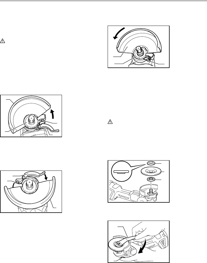
Installing or removing depressed center
wheel or multi disc (optional accessory)
WARNING:
• When using a depressed center wheel or multi
disc, the wheel guard must be fitted on the tool so
that the closed side of the guard always points
toward the operator.
•
Only actuate the shaft lock when the spindle is not
moving.
1
2
3
015088
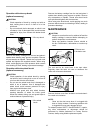
Mount the inner flange onto the spindle. Fit the wheel/disc
on the inner flange and screw the lock nut onto the spindle.
1
2
015089
To tighten the lock nut, press the shaft lock firmly so that
the spindle cannot revolve, then use the lock nut wrench
and securely tighten clockwise.
To remove the wheel, follow the installation procedure in
reverse.
1. Wheel guard
2. Bearing box
3. Screw
1. Lock nut wrench
2. Shaft lock
1. Lock nut
2. Depressed
center wheel
3. Inner flange
1. Screw
2. Lever
3. Wheel guard
1. Wheel guard
2. Bearing box
3. Screw
4. Lever