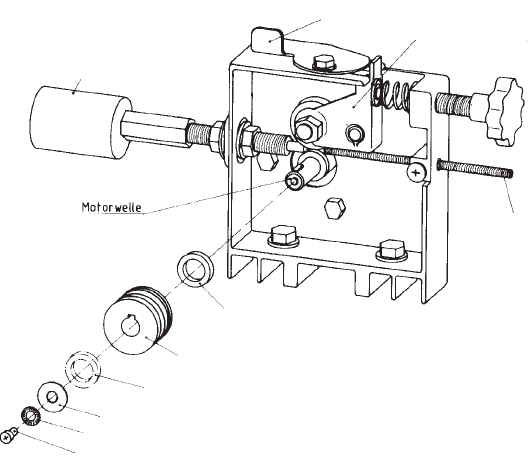
4.2 Wire Feed Set-up
5 Welding Stainless Steel and Aluminium
This MIG welding machine is factory set for welding low-carbon steel. Use a mixed gas (e.g. Ar 99.988 %).
4.3 Feeding the Wire into the Torch
Place the wire through the spiral guide tube across the feed roller into the central coupling's wire intake. Bring
tension roller in position and set tension.
Unscrew the gas shroud from the swan neck by turning clockwise, contact tip by turning counter-clockwise. Switch
the machine on, set wire feed speed to lowest speed and press the torch's trigger switch until the wire protrudes
approx. 2.5 cm/1 in. from the swan neck. Replace contact tip and gas shroud.
Please note that all machines as standard fitted for 0.6; 0.8 and 1.0 mm electrode wire. If a wire of a different
diameter is to be used, the contact tip must be exchanged against on of matching size and the feed roller installed
with the corresponding groove size opposite the wire intake.
Central coupling
Lever
Tension roller
Spiral guide
tube
Spacer
Wire Ø 1,0/1,2
Feed roller
Spacer
Wire Ø 0,6/0,8
Washer
Serrated lock washer
Screw
The feed roller is fitted with four pilot grooves for
wire diameters 0.6/0.8/1.0/1.2 mm.
To adapt the feed roller to the wire size used,
first release the tension roller from the feed roller
by pushing the lever back.
For 1.0 or 1.2 mm wire the corresponding outer
groove is required. Place spacer washer onto
drive shaft, then feed roller so that the required
groove size is in line with the wire intake of the
central goupling. For 0.6 or 0.8 mm wire the
inner grooves are required. Place feed roller
first onto shaft, followed by the spacer washer.
After spacer and feed roller have been mounted
as required secure in place with the washer,
serated lock washer and screw. If required, the
two nuts on the central coupling's wire intake
can be loosened and its position centered to the
groove.
Return the tension roller onto the feed roller an
set to required tension by means of the setting
screw.
Setting of Wire Feed Speed
Fine tuning of setting during welding is actually carried out.The feed speed is correct when the arc burns with a steady hum.
170/30 TL Combi
Welding Step Ø 0.6 SG 2 Ø 0.8 SG 2
230 V 400 V 230 V 400 V
1 5 6 4.5 5.5
2 6 856
3 8106 6.5
4101277
5131588
6161899
170/30 TL
Welding Step Ø 0.6 SG 2 Ø 0.8 SG 2
1 5 4.5
2 6 5.5
3 8 6
410 7
515 8
618 9
180/35 ET Combi
Welding Step Ø 0.6 SG 2 Ø 0.8 SG 2
230 V 400 V 230 V 400 V
1 3 53 4
2 4.5 6.5 3.5 4.5
3 5.5 8 4 6
4 6.5 11 5 7
5 9176 8.5
61320711
200/35 ET
Welding Step Ø 0.6 SG 2 Ø 0.8 SG 2
12 1.5
23 2,5
35 3.5
47 5.5
5 15.5 10.0
6- 13.0
230/40 ET
Welding Step Ø 0.6 SG 2 Ø 0.8 SG 2
13 2.5
24 3.5
36 4.5
48 6.5
5 16.5 11.0
6- 14.0


