


ENGLISH en
9
See page 2.
1 Battery pack
2 Capacity and signal indicator
3 Capacity indicator button
4B
attery pack release button
5 Electronic signal indicator
6 Dust filter
7 Sliding
on/off switch
8 Additional handles
9Sanding belt
10 Sanding head
11 Arrow (direction of sanding belt motion)*
12 Adjuster screw (for setting the tension force)
13 Release lever
14 Sanding belt roller
15 Pressure spring
16 Screw (see chapter 6.6 and 6.7)
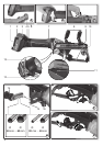
6.1 Dust filter
Always fit the dust filter if the surroundings are
heavily polluted (6).
The machine heats up faster when the dust
filter is fitted (6). It is protected by the elec-
tronics system from overheating (see chapter9.).
To fit:
See page 2, fig. A. Attach the dust filter (6) as
shown.
To remove:
Holding the dust filter at the edges, raise it slightly
(6) and then pull it downwards and remove.
6.2 Rotating battery pack
See illustration B on page 2.
The rear section of the machine can be rotated 270°
in three stages, thus allowing the machine's shape
to be adapted to the working conditions. Only
operate the machine when it is in an engaged posi-
tion.
6.3 Battery pack
Charge the battery pack before use (1).
If performance diminishes, recharge the battery
pack.
The ideal storage temperature is between 10°C and
30°C.
"Li-Power" li-ion battery packs have a capacity and
signal indicator: (2)
- Press the button (3), the LEDs indicate the charge
level.
- If one LED is flashing, the battery pack is almost
flat and must be recharged.
6.4 Removing and inserting the battery pack
Removal:
Press the battery pack release (4) button and pull
the battery pack (1) down
.
Inserting:
Slide in the battery pack (1) until it engages.
6.5 Turning the sanding head (10) to operat-
ing position
- Open the release lever (13).
- Turn the sanding head (10) to the required oper-
ating position.
- Close the release lever (13), applying force until it
hits the limit stop.
The tension force has been set correctly when
the release lever can only be moved as far as
the limit stop when force is applied (13) and when
the sanding head (10) is securely attached to the
device.
- If necessary, you can adjust the tension force of
the tension lock by twisting the adjuster screw (12)
(when the release lever is open (13)).
6.6 Adjusting to the tube diameter
a) Choose the adjustable range (coarse setting)
See illustration D on page 2.
The screw (16) can be inserted in 2 different screw
threads. This provides 2 different adjustable ranges
for the sanding belt roller (14).
Note: When extracting screw (16), be careful not to
lose the inner pressure spring (15).
b) Adjust the sanding belt roller (fine setting)
See illustration E on page 2.
- Slacken the screw (16) sufficiently, but do not
remove it entirely.
- Tilt the sanding belt roller (14) in the direction of
the arrow and adjust.
- Tighten the screw (16) again.
- Adjust the belt run (see chapter 6.7).
6.7 Adjusting the belt run
See page 2, illustration F.
Using screw (16), adjust the sanding belt
(with the machine running) so that it runs
centrally on the sanding belt roller.
7.1 On/Off switch, continuous activation
See illustration C on page 2.
Always guide the machine with both hands.
Switch the machine on first before mounting it
on the workpiece.
The machine must not be allowed to draw in
additional dust and shavings. When switching
the machine on and off, keep it away from dust
deposits.
After switching off the machine, only place it
down when the motor has come to a standstill.
In continuous operation, the machine
continues running if it is forced out of your
hands. Therefore, always hold the machine using
the handles provided, stand in a safe position and
concentrate.
5. Overview
6. Initial Operation
7. Use