


ENGLISH en
9
Hz ...........hertz
.../min......revolutions per minute
~ ............. alternating current
...........direct current
n.............. rated speed
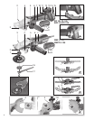
See page 2.
1 Support flange
2Spindle
3 Spindle locking button
4 Safety guard
5 Additional handle / Additional handle with vibration
damping *
6 Sliding
on/off switch
7Handle
8Switch-on lock *
9 Trigger *
10 Electronic signal indicator
*
11 B
attery pack release button *
12 Capacity indicator button *
13 Capacity and signal indicator *
14 Battery pack*
15 Dust filter
*
16 Clamping nut *
17 2-hole spanner *
18 Lever for safety guard attachment
* depending on equipment/not in scope of delivery
5.1 For mains powered machines only
Before plugging in the device, check that the
rated mains voltage and mains frequency, as
specified on the rating label, match your power
supply.
Always install an RCD with a max. trip current
of 30 mA upstream.
5.2 For cordless machines only
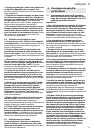
Dust filter
Always fit the dust filter if the surroundings are
heavily polluted (15).
The machine heats up faster when the dust
filter is fitted (15). It is protected by the elec-
tronics system from overheating (see chapter9.).
Attaching:
See page 2, illustration A.
Attach dust filter (15) as shown.
To remove:
Holding the dust filter (15) by the upper
edges, raise it slightly and then pull it downwards
and remove.
Rotating battery pack
See illustration B on page 2.
The rear section of the machine can be rotated 270°
in three stages, thus allowing the machine's shape
to be adapted to the working conditions. Only
operate the machine when it is in an engaged posi-
tion.
Battery pack
Charge the battery pack before use (14).
If performance diminishes, recharge the battery
pack.
The ideal storage temperature is between 10°C and
30°C.
"Li-Power" li-ion battery packs have a capacity and
signal indicator: (13)
- Press the button (12), the LEDs indicate the
charge level.
- If one LED is flashing, the battery pack is almost
flat and must be recharged.
Removing and inserting the battery pack
To remove:
Press the battery pack release button
(11) and pull the battery pack (14) downwards.
To fit:
Slide in the battery pack (14) until it engages.
5.3 Attaching the additional handle
Always work with the additional handle
attached (5)! Attach the additional handle on
the left or right of the machine and secure.
5.4 Install safety guard
For safety reasons, always use the safety
guard provided for the respective wheel! See
also chapter 10.
Safety guard for grinding
Designed for work with roughing wheels, flap
sanding pads, diamond cut-off wheels.
See page 2, illustration E.
- Place the safety guard (4) in the position indi-
cated.
- Push the lever and turn the safety guard until the
closed section is facing the operator.
- Release the lever and turn the safety guard
until the lever engages.
- Make sure that the guard is seated securely: the
lever must engage and you should not be able to
turn the safety guard.
Use only accessories that
are covered by at least 3.4
mm by the safety guard.
Before carrying out any modifications, remove
the battery pack from the machine and pull the
mains plug from the socket. The machine must be
switched off and the spindle must be at a standstill.
For reasons of safety, attach the parting guard
before performing parting work (see chapter
10. Accessories).
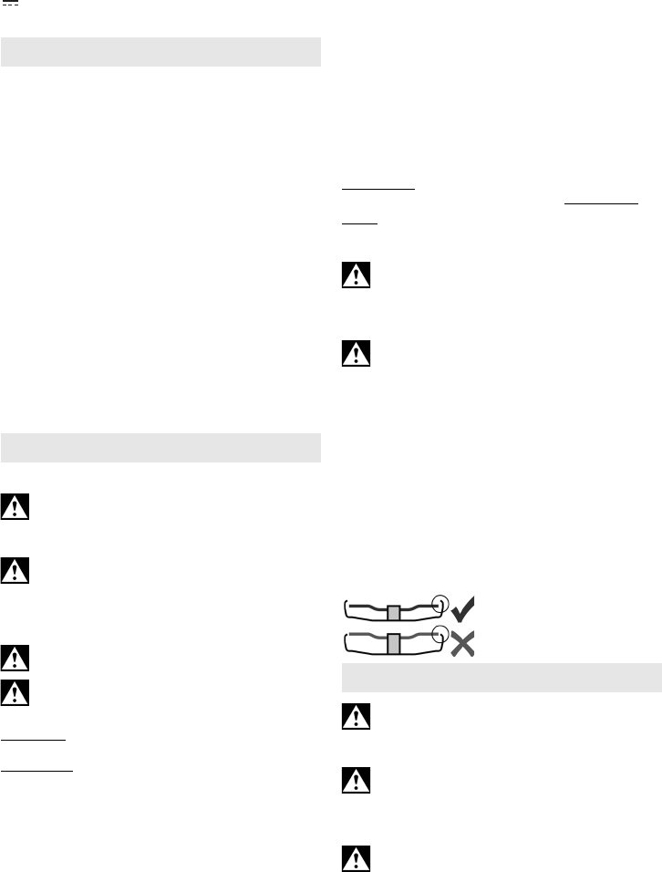
6.1 Locking the spindle
Press in the spindle locking button (3) only
when the spindle is stationary!
- Press in the spindle locking button (3) and turn the
spindle (2) by hand until you feel the spindle
locking button engage.
4. Overview
5. Initial Operation
6. Attaching the grinding wheel