


8
FINAL ASSEMBLY
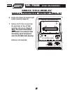
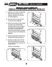
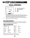
Make wiring connections using the EIA color code chart shown below and the instructions included with the head
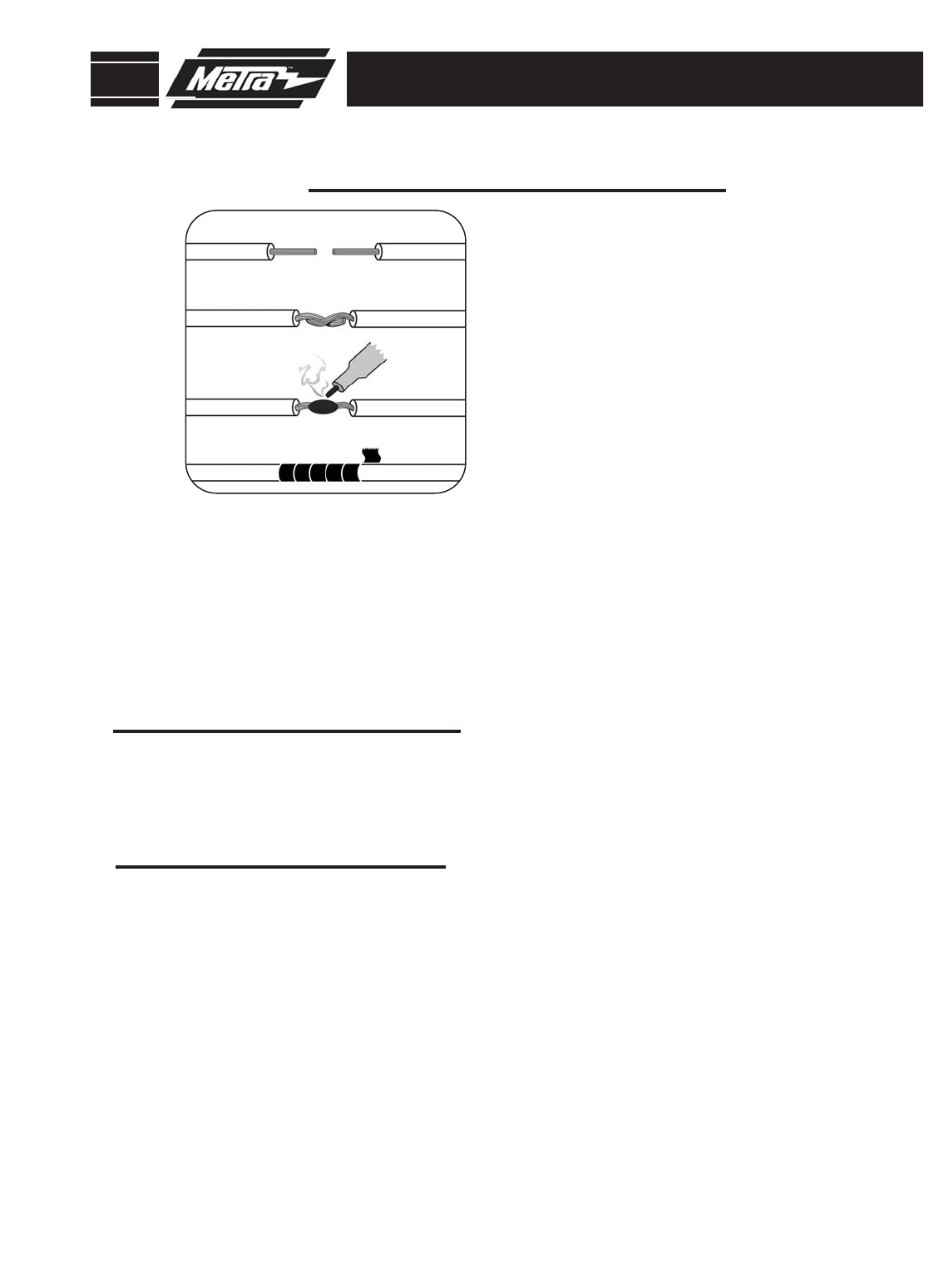
unit. Metra recommends making connections as shown below; Strip, Splice, Solder, Tape. Isolate and individually
tape off ends of any unused wires to prevent electrical short circuit.
FINAL WIRING CONNECTIONS
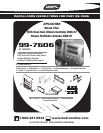
99-7606
FINAL ASSEMBLY
12V Ignition / Acc . . . Red
12V Batt / Memory . . Yellow
Ground . . . . . . . . . . . Black*
Power Antenna . . . . . Blue
Amp Turn-On . . . . . . Blue / White
Amp Ground . . . . . . . Black / White
Illumination. . . . . . . . Orange
Dimmer . . . . . . . . . . Orange / White
Right Front (+) . . . . . Gray
Right Front (-) . . . . . . Gray/ Black
Left Front (+) . . . . . . White
Left Front (-) . . . . . . . White / Black
Right Rear (+). . . . . . Violet
Right Rear (-) . . . . . . Violet / Black
Left Rear (+). . . . . . . Green
Left Rear (-) . . . . . . . Green / Black
METRA / EIA WIRING CODE
*NOTE: When a Black wire is not present, ground radio to vehicle chassis.
All colors may not be present on all leads due to manufacturer’s specifications.
1
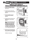
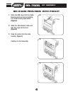
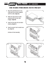
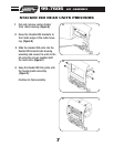
Locate the factory wiring harness in the dash. Metra recommends using the
proper mating adapter and making connections as shown. (Isolate and individually
tape off the ends of any unused wires to prevent electrical short circuit.)
2
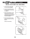
Re-connect the negative battery terminal and test the unit for proper operation.
3
Reassemble in reverse order of disassembly.
A
A) Strip wire ends back 1/2"
B) Twist ends together
C) Solder
D) Tape
B
C
D