


OM-1213 Page 12
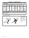
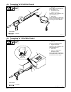
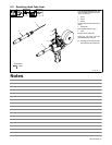
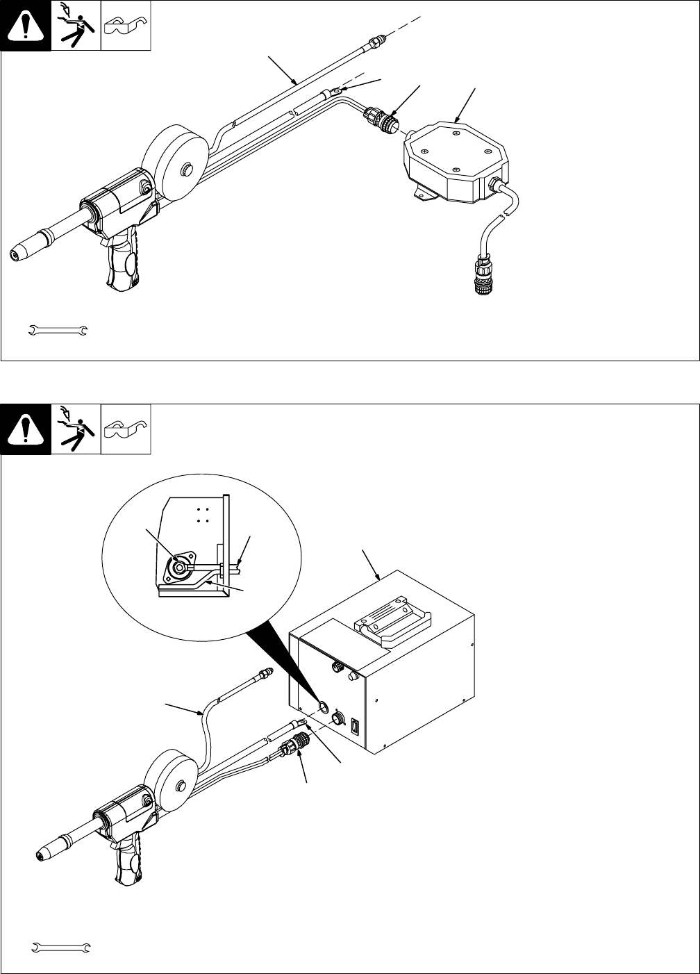
4-5. Connecting To 24 Volt Weld Control
150 917-G
1 Gas Hose
Connect fitting to regulator/flowme-
ter (see Section 4-7).
2 24 Volt Weld Control
3 Trigger Control Cord
Insert plug into receptacle, and
tighten threaded collar.
4 Weld Cable
Connect to positive (+) weld output
terminal on welding power source
according to its Owner’s Manual.
Tools Needed:
1-1/8, 5/8 in
1
2
3
4
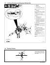
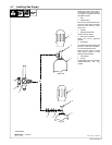
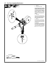
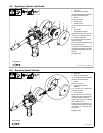
4-6. Connecting To 115 Volt Weld Control
Ref. 149 549-A / 149 966-J
1 115 Volt Weld Control
2 Gas Hose
Connect to regulator/flowmeter.
3 Trigger Control Cord
Insert plug into receptacle, and
tighten threaded collar.
4 Weld Cable
5 Positive (+) Weld Output
Terminal In Control
Connect weld cable to positive (+)
weld output terminal in weld control.
Reinstall weld control wrapper.
Left Side
Wrapper Off
5
6
1
2
3
4
3
Tools Needed:
1-1/8, 5/8 in