


OM-227 674 Page 16
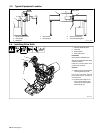
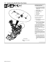
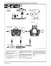
3-10. Threading Welding Wire And Adjusting Pressure Drive Setting
Ref. 804 391-A / Ref. 804 190-A / Ref. 156 798
Tools Needed:
1 Drive Roll Pressure Adjustment Lever
2 Notch In Lever (Indicates Pressure
Settings)
Pressure drive settings range from 1 to 8 with
8 being the maximum setting.
. For aluminum (soft) wire set pressure
drive setting at 4 or below.
. Be sure that gun has proper size liner for
the welding wire size.
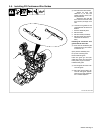
When installing gun, the liner should extend
into the PD continuous guide (or exit guide if
used) as far as possible without interfering
with the guide.
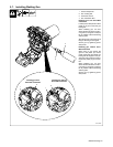
Install gun. Lay gun cable out straight. Cut off
end of wire. Push wire through guide up to
drive rolls; continue to hold wire. Press Jog
button to feed wire out gun.
To adjust drive roll pressure, hold nozzle
about 2 in (51 mm) from nonconductive
surface and press gun trigger to feed wire
against surface. Adjust pressure drive lever
so wire does not slip. Do not overtighten. If
contact tip is completely blocked, wire should
slip at the feeder (see pressure adjustment
above.)
Cut wire off.
NONCONDUCTIVE
SURFACE
NONCONDUCTIVE
SURFACE
No Wire Slip
Wire Slips
Drive Rolls
End Of Liner
Back Of Gun Cable
1
Adjust tension.
. Pressure assembly
door not shown.
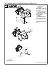
2
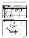
POWER
PURGE
6 in
(150 mm)
Hold wire tightly to keep it
from unraveling.
V
Turn on power at welding power source. Pull and hold wire; cut off end.
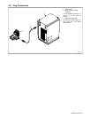
ON
OFF
JOG
Welding Power Source