


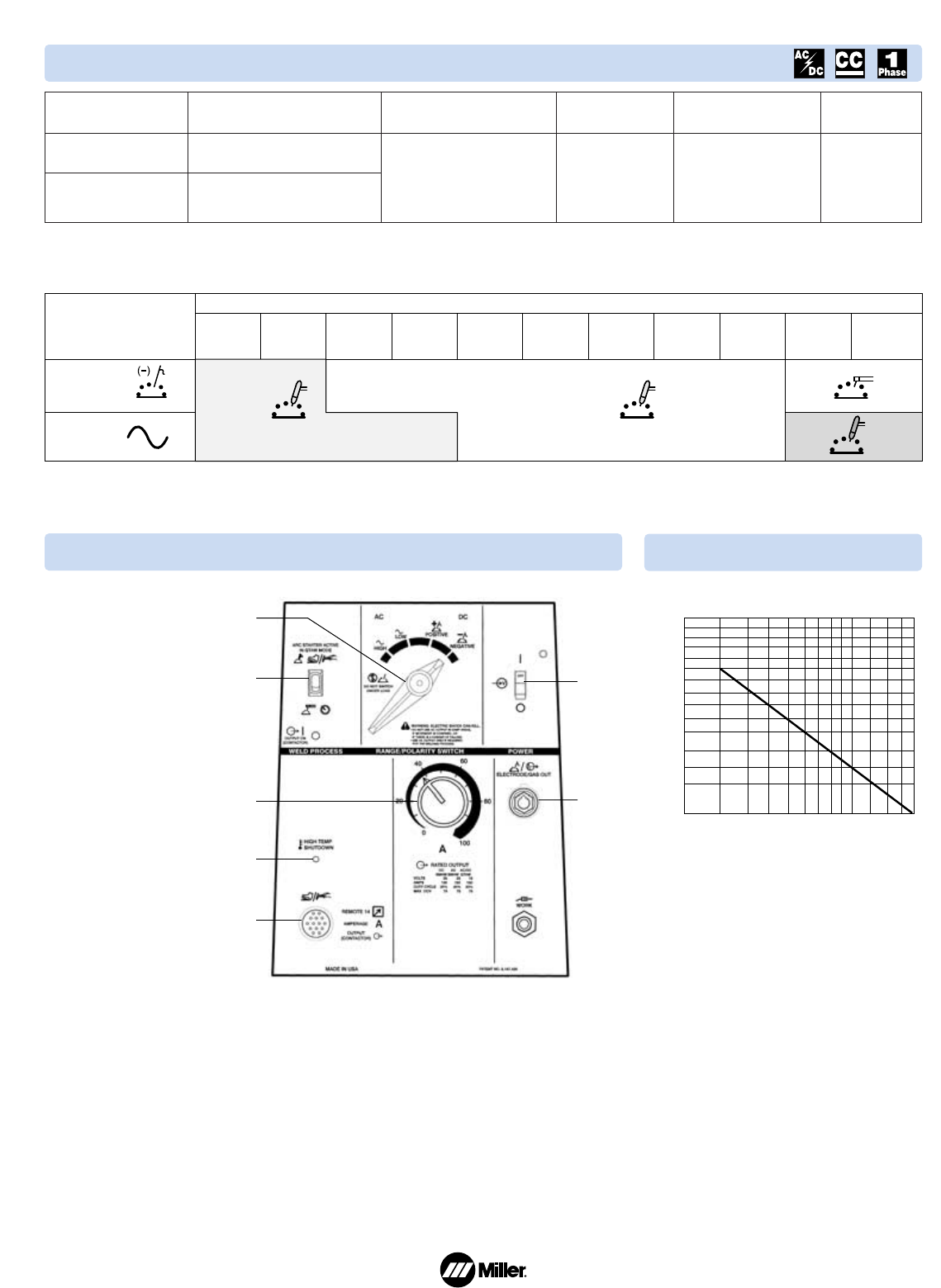
200
150
100
60
80
15 20 25 30 40 50 7060 80 90100
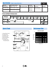
WELDING AMPERES
% DUTY CYCLE
DUTY CYCLE CHART
1
2
4
3
5
7
6
2
Control Panel
Performance Data
Specifications
(Subject to change without notice.)
1. Range/Polarity Switch
2. Process Switch
3. Amperage Control
4. High Temp Light
5. Remote Receptacle
6. Power Switch
7. International Flow-
Through Receptacle
Rated Output
at 20% Duty Cycle
TIG:150 A at 15 VDC
150 A at 15 VAC
Stick:130 A at 25 VDC
150 A at 25 VAC
Welding Amperage Range
AC High AC Low DC
TIG Welding Range
50–165 20–50 30–160
Stick Welding Range
35–165 20–50 25–130
Max. Open-Circuit Voltage
78
Input Amps
at Rated Output
200 V
60 A
230 V 52 A
460 V 33 A
380 V 39 A
415 V 36 A
Dimensions
H: 18 in (457 mm)
W: 13 in (330 mm)
D: 25-1/2 in (648 mm)
Net Weight
140 lb (64 kg)
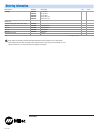
Process and Material Thickness Guide
Material and
Weld Output
22 ga
0.033 in
0.8 mm
Steel or
Stainless Steel
Aluminum
20 ga
0.036 in
0.9 mm
18 ga
0.048 in
1.2 mm
16 ga
0.06 in
1.5 mm
14 ga
0.07 in
1.8 mm
12 ga
0.1 in
2.5 mm
11 ga
0.125 in
3.2 mm
10 ga
0.14 in
3.6 mm
6 ga
0.186 in
4.8 mm
2 ga
0.25 in
6.3 mm
—
0.25
+
in
6.3
+
mm
Material Thickness
Electrode Negative
DCEN
TIG (GTAW)
TIG
(GTAW)
Stick
(SMAW)
AC
Not
Recommended
With
DCEP
Output
Difficult
TIG (GTAW)
Recommended