


3
Big 40
®
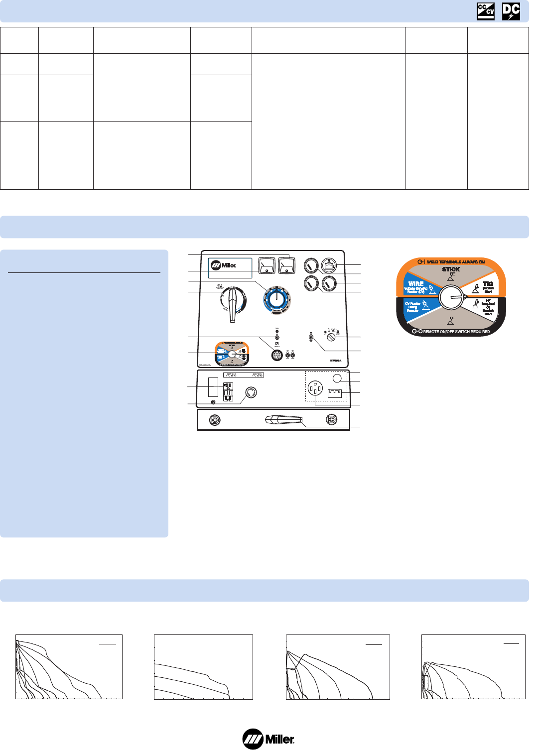
Diesel CC/CV Control Panel
W
elding
Mode
CC/DC
CV/DC
CC/AC
(Deluxe
Model)
Big 40
®
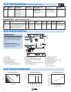
Diesel CC/CV Specifications
(Subject to change without notice.)
Max. Open-
Circuit Voltage
95
56
65
W
eld Output
Range
20–550 A
14–40 V
15–375 A
Weld Output Rated
at 104˚F (40˚C)
400 A at 36 VDC (14.4 kW),
100% Duty Cycle
450 A at 38 VDC (17.1 kW),
60% Duty Cycle
500 A at 34 VDC (17 kw),
40% Duty Cycle
300 A at 32 VAC (9.6 kW),
100% Duty Cycle
335 A at 33 V (11.1 kW),
60% Duty Cycle
375 A at 35 V (13.1 kW),
40% Duty Cycle
Generator Power Output Rated
Peak: 5000 watts
Continuous: 4000 watts,
34/17 A,
120/240 VAC, 60 Hz while welding
Deluxe Model Additional Power Plant:
1-phase, 12 kW, 50 A, 120/240 VAC, 60 Hz; or
3-phase, 15 kW, 36 A, 240 VAC, 60 Hz while
not welding
Net Weight
(without fuel)**
1545 lb
(701 kg)
Dimensions*
H: 43 in
(1092 mm)
W: 28-1/2 in
(724 mm)
D: 64-7/16 in
(1637 mm)
NEMA EWI (ANSI C87.1) Class (1) output ratings. *Additional 7 in (178 mm) to top of exhaust. **Additional 190 lb (86 kg) when fuel tank is full.
Additional Features
A multi-colored process selector control
allows quick and easy process changes
without having to use multiple switches.
Heavy-Duty Design — The Vault design
provides enhanced arc characteristics that
include more dig in the Stick mode with
smoother and lower amper age in the TIG
mode. Along with the superior welding
performance, the Vault provides the ultimate
reliability in the harshest of environments.
A hermetically-sealed vault protects Miller
control boards from dust, moisture, and
tough environmental elements. Extreme
con ditions will not cause the output to
change, eliminating the need to periodically
turn up the heat.
15,000 watt generator option for stand-by
power generation adds 15 kW, three-phase,
240 volt power to CC/CV units. 12 kW,
120/240 volt, single-phase power from a
50 amp receptacle while not welding.
Big 40
®
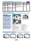
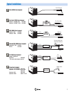
Diesel CC/CV Performance Data
DC VOLTS
DC AMPERES
100
80
60
40
20
0
0 100 200 300 400 500 600 700 800 900 1000
Ranges
155 – 450
Max
115 – 320
40 – 90
75 – 195
0 100 200 300 400 500
Ranges
35 – 250
60 – 365
25 – 155
15 – 75
DC AMPERES
20
0
40
60
80
100
DC VOLTS
0
20
40
60
80
100
0 50 100 150 200 250 300 350400450 500
Ranges
55 – 350
35 – 205
25 – 105
15 – 45
AC AMPERES
AC VOLTS
CC/CV VOLT/AMP CURVES
STICK MODE
CC/CV VOLT/AMP CURVES
TIG MODE
CC/CV VOLT/AMP CURVES
AC TIG MODE
DC VOLTS
DC AMPERES
100
80
60
40
20
0
0 100 200 300 400 500 600 700 800 9001000
MAX
MIN
CC/CV VOLT/AMP CURVES
MIG MODE
4
5
9
10
12
11
13
15
16
17
18
14
6
7
8
3
1
2
19
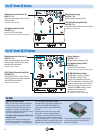
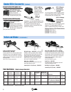
5
Process/Contactor Selector Switch
1. DC Ammeter*
2. DC Voltmeter*
3. Amperage/Voltage Adjust Control
4. Ampere Range Switch
5. Amperage/Voltage Adjust Switch and Remote
Amperage/Voltage Adjust Receptacle
6. Process/Contactor Selector Switch
7. 120 VAC, 20 A GFCI Duplex Receptacle
8. 240 VAC, 30A TwistLock Receptacle
(NEMA L6-30)
9. Fuel Gauge/Hour Meter/Oil Change Interval/
Engine Shutdown Indicator
10. Engine Oil Pressure Gauge
11. Battery Voltmeter*
12. Engine Coolant Temperature Gauge
13. Engine Control Switch
14. Starting Aid Switch
15. 3-Phase Power Generator Option*
16. Strain Relief*
17. 50 A, 3-Phase Circuit Breaker
18. 50 A, 120/240 V Receptacle
(NEMA 14-50)*
19. AC/DC Polarity Switch*
*Optional on select models.