


OM-491 Page 13
SECTION 4 − INSTALLATION
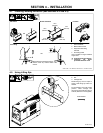
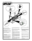
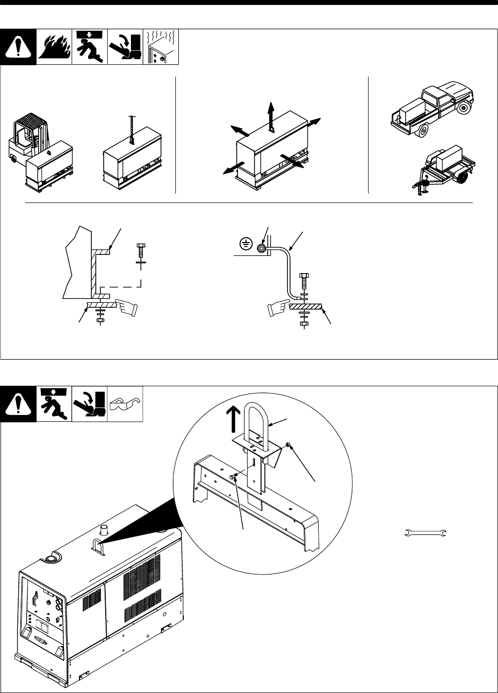
4-1. Installing Welding Generator (See Sections 4-2 And 4-3)
install1 3/96* − Ref. 800 652 / Ref. 800 477-A / 158 936-A / 0854
1
2
Electrically bond generator frame to
vehicle frame by metal-to-metal
contact.
GND/PE
3
4
1 Generator Base
2 Metal Vehicle Frame
3 Equipment Grounding
Terminal
4 Grounding Cable
Use #10 AWG or larger insulated
copper wire.
Y If unit does not have GFCI re-
ceptacles, use GFCI-
protected extension cord.
2
OR
18 in
(460 mm)
18 in
(460 mm)
18 in
(460 mm)
18 in
(460 mm)
18 in
(460 mm)
OR
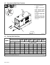
Movement Airflow Clearance Location
Grounding
OR
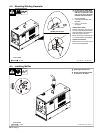
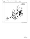
4-2. Using Lifting Eye
Ref. 802 169-A
1 Lifting Eye
2 Nut
3 Carriage Bolt
Raise lifting eye until it snaps in
place. Lower lifting eye when not
needed.
To lock the lifting eye in the upright
position, insert carriage bolt
through slot in bracket and secure
with nut (bolt and nut not supplied).
Tools Needed:
2
1
3